Step by Step Skeletal Animation in C++ and OpenGL, Using COLLADA
Part 2
Last update December 2010
I am happy to receive donations for maintaining this site, if you would like to donate click bellow
Level: Beginner to Intermediate
Before you start reading the implementations part, if you haven't read the first part of this tutorial(s), which explains COLLADA documents in detail, you should follow the link below.
You should have seen the following structure. In part 1
1) Reading and Understanding COLLADA documents. (high level overview of COLLADA)
2) Actual Implementations in C++ using OpenGL, of what we learn in Part 1
The one that your are reading now is the second part which has further two parts,
1) Implementation part related to the Exporter for COLLADA
2) Implementation part related to the skeletal animation in C++ using OpenGL
As far as the implementation of skeletal animation is concerned, we will Use OpenGL and C++, but the exporter which is used to export Data from COLLADA documents into my own Binary format (.CBA), I have written in C# (C Sharp). I could have written that in C++, but I was too lazy to write my own implementation of XML readers, while C# has very good implementation for that. And the free API for XML parsing (tinyXML) has a lot of issues which I was not really ready for. So I wrote my COLLADA exporter in C# and I create my binary file format which I call CBA files, from my exporter. CBA means COLLADA Binary Assets :) and later I import this file in C++ using a CBA reader API. Now this introduced a lot of problems for me, like I have to maintain almost similar code twice once in C# for my exporter and Once in C++ for my importer. So it would be better that you don't use my exporter and write your own Exporter in what ever language you prefer. And that would also help you understand the COLLADA documents in depth.
Part 2.1:
Implementation of Exporter for COLLADA, written in C#
Implementation of Skeletal Animation in COLLADA documents
As we have discussed in the introduction part, this tutorial is split in to two parts, I assume you have already read first one general introduction to COLLADA documents which is irrespective of any programming language Part 1: COLLADA documents. Now we would define the structure in which we can read the COLLADA document. Please bear in mind that this exporter which I have written in C# is one of my worst ever codes, I wrote everything very quick and didn't had any time to plan and design before code. So you will see a lot of hacks every where :) but it is of course recommended that you write your own exporter. One other thing you should remember is that, this part of part 2 will try to read the COLLADA document but will not change the structure (schema) of the data; every thing is read as it is from COLLADA, and when we will write our custom format out of it, we will just read those things which are really necessary.
Reading Geometry Data from COLLADA document
Click here to go to: Introduction section in part 1, for this section of part 2
In the introduction section of part 1, we discussed the following libraries and nodes which are related to this section and which will be parsed and used,
<library_geometries>
<geometry>
<mesh>
<souce>
<technique_common>
<float_array> and <NAME_array>
<accessor>
<param>
<triangles>
<vertices>
<input>
<p>
Now you might know that some of the nodes are part of the Core COLLADA, which means, that they can appear in many places and many libraries in COLLADA. So you should define a structure for those nodes with common names so that they can be used for all kinds of purposes, for example a <source> node can be used for Vertices, Animation, Texture Coordinates and Vertex Weights or any other kinds of data. This is something that I forgot in my C# implementation, and later I was not able to re-factor :) Remember my hacky bits of code :).
So if I were to define a class in which I can read the Geometry data of a COLLADA document I would do something like follows.
class COLLADA
{
private:
GeometryLibrary m_GeometryLibrary;
};
Where GeometryLibrary would be defined as follows.
class GeometryLibrary
{
Vector<Geometry> m_Geometries;
};
And now we define Geometry as follows.
class Geometry
{
Mesh m_Mesh;
};
The rest of the Libraries are not important at this point so we will not discuss them. All the other types of classes which are needed to store different nodes from COLLADA are listed as follows. And this is the simplest implementation you can make. I am not considering optimizations and inheritance etc. and there might be a lot of opportunities for restructuring and optimizations. For example as we know a source can have one type of array node, which could be <float_array>, <NAME_array> or any other type of array, in my implementation I am using different classes for each, you might want to create one class called Array or BaseArray and then derive each type of Array from it with specialize values.
//----------------------------------------------//
class Float_Array
{
unsigned int m_Count;
string m_ID;
float *m_Floats;
};
//----------------------------------------------//
class Name_Array
{
unsigned int m_Count;
string m_ID;
string *m_Names;
};
//----------------------------------------------//
class Param
{
string m_Name;
string m_Type;
};
//----------------------------------------------//
class Accessor
{
string m_Source;
unsigned int m_Count;
unsigned int m_Stride;
Vector<Param> m_Params;
};
//----------------------------------------------//
class Technique_Common
{
Accessor m_Accessor;
};
//----------------------------------------------//
class Source
{
string m_ID;
Float_Array m_Float_Array;
Name_Array m_Name_Array;
Technique_Common m_TechniqueCommon
};
//----------------------------------------------//
class Input
{
string m_Semantic;
string m_Source;
string m_Offset;
string m_Set;
};
//----------------------------------------------//
class Vertices
{
string m_ID;
Vector<Input> m_Inputs;
};
//----------------------------------------------//
class P
{
unsigned int m_Count;
unsigned short *m_Indices;
};
//----------------------------------------------//
class Triangles
{
unsigned int m_Count;
string m_Material;
Vector<Input> m_Inputs;
P m_P;
};
//----------------------------------------------//
class Mesh
{
Vector<Source> m_Sources;
Vertices m_Vertices;
Vector<Triangles> m_Triangles;
};
//----------------------------------------------//
Now using those files we will store the Geometry data from COLLADA documents in a COLLADA Class Object. How you can read all those nodes is another story, you can either use C#'s XML parsers or use TinyXML or any other XML parser to load and parse COLLADA documents, you can also write your own XML parser if you have enough time. But I would suggest using an existing one rather writing your own, since the goal is to read COLLADA documents not XML files.
By now you should have all the Data related to displaying the model in 3D scene, you can start from <triangles> node and render all the triangles using OpenGL.
Reading Texture filename from COLLADA document
Click here to go to: Introduction section in part 1, for this section of part 2
In the introduction section of part 1, we discussed the following libraries and nodes which are related to this section and which will be parsed and used,
<library_images>
<image>
<init_from>
Its all again up to you how you want to read the texture file name, once you know where to find it. In the simplest form I would create a class for LibraryImages as well in the COLLADA Class and read the <image> in to it and so on. So the refined implementation for Class COLLADA will become as follows.
class COLLADA
{
private:
GeometryLibrary m_GeometryLibrary;
ImagesLibrary m_ImagesLibrary;
};
Where ImagesLibrary would be defined as follows.
class ImagesLibrary
{
Vector<Image> m_Images;
};
And now we define Image as follows.
class Init_From
{
string m_Filename;
};
class Image
{
Init_From m_Init_From;
};
Reading Materials from COLLADA document
Click here to go to: Introduction section in part 1, for this section of part 2
In the introduction section of part 1, we discussed the following libraries and nodes which are related to this section and which will be parsed and used,
<triangles>
<library_materials>
<material>
<instance_effect>
<library_effects>
<effect>
<phong> or <blin>
<profile_COMMON>
<technique>
<ambient>
<diffuse>
<specular>
<emission>
<shininess>
<transparency>
<color>
If you have read the previous sections of this part 2, and introduction part for this section you should be able to define the structure for this section by yourself, so I will not discuss it, since its getting repeated.
Reading Skeleton from COLLADA document
Click here to go to: Introduction section in part 1, for this section of part 2
In the introduction section of part 1, we discussed the following libraries and nodes which are related to this section and which will be parsed and used,
<library_visual_scenes>
<node>
<instance_controller>
<skeleton>
<visual_scene>
<matrix>
In the introduction part we discussed how to read the skeleton from <visual_scene> so I assume you should be able to define the structure for reading that data. But I used another approach myself. Which I think is the simplest way of reading Skeleton from COLLADA documents. And before discussing that, you need to read the next section in the introduction part.
Reading Skinning information from COLLADA document
Click here to go to: Introduction section in part 1, for this section of part 2
In the introduction section of part 1, we discussed the following libraries and nodes which are related to this section and which will be parsed and used,
<library_controllers>
<controller>
<skin>
<source>
<param>
<accessor>
<technique_common>
<NAME_array>
<float_array>
<node>.
<vertex_weights>
<input>
<vcount>
<v>
What I do for reading the skeleton from COLLADA documents is that I read the <controller>, and for all the Bone SIDs I check in the Visual Scene and find his parent and Joint Matrix, there, and I read the Inverse Bind matrix from the <controller>. And that’s all what we need. As you might remember we took an assumption that all the joints must be attached to the skin. In that case you don't have to read the <instance_controller> node in the <visual_scene> and you can read Bone IDs from <controller> and find them in <visual_scene>. It require a little work to find the node in <visual_scene> and find his parent etc, but once you have started working with COLLADA nodes it should not be hard for you.
Reading Animation data from COLLADA document
Click here to go to: Introduction section in part 1, for this section of part 2
In the introduction section of part 1, we discussed the following libraries and nodes which are related to this section and which will be parsed and used,
<library_animations>
<animation>
<source>
<sampler>
<channel>
<visual_scene>
By now you should be quite an expert to define structure for loading this data in to it. But I would also give you a hint. Your COLLADA Class should look as follows, after reading all those sections.
class COLLADA
{
private:
GeometryLibrary m_GeometryLibrary;
ImagesLibrary m_ImagesLibrary;
EffectsLibrary m_EffectsLibrary;
MaterialLibrary m_MaterialLibrary;
ControllerLibrary m_ControllerLibrary;
AnimationLibrary m_AnimationLibrary;
VisualSceneLibrary m_VisualSceneLibrary;
};
Where AnimationLibrary would be defined as follows and all the other libraries must have been defined by you.
class AnimationLibrary
{
Vector<Animation> m_Animations;
};
And now we define Animation as follows.
class Animation
{
string m_ID;
Vector<source> m_Sources;
Vector<sample> m_Samples;
Vector<channel> m_Channels;
};
And now you should be able to define "sample" and "channel" classes. You can also write a structure where you do some other processing already on these <animation> nodes, and only keep the list of channels, where you reference the sampler targeted by this channel and then in "sample" you save references to the <sources> that are targeted or used by that sample. This processing we have to do sooner or later so it's your choice when and where you want to do it. But as we discussed in the beginning of this part, that we will not change the structure of COLLADA but read as it is so you might not want to do it now.
Please not that I am not giving you actual code for reading from COLLADA documents, since that depends on what language you use to read XML files. If you have read the first part of these tutorials and you have created the structure properly, you should be able to read the data very easily using any XML parser. So I will not go in that much detail of implementation. And will let you do the job yourself.
Once we have finished reading the COLLADA document, we are ready to write the CBA file, which will be explained in the following section, in case you don't want to write CBA file you can write your own "what ever" format and then read it accordingly.
CBA file format
The CBA file format is a very easy and simple to read and write file format. Geometry and skeletal data i.e. Vertex Weights etc, is saved in index form, which means, the whole data is saved once in a long floats array and then that float array is referenced with indices from the places where the data is needed. This saves space when you don't want to save repeated vertex attributes for example. In a typical 3D model one vertex can be used by many triangles, and instead of saving that vertex many times for each triangle, its better to save it once and save its index for each triangle. That’s how all the data is saved in COLLADA and CBA file will use the same structure since it saves a lot of space as well as sending this data to OpenGL is also easy and efficient.
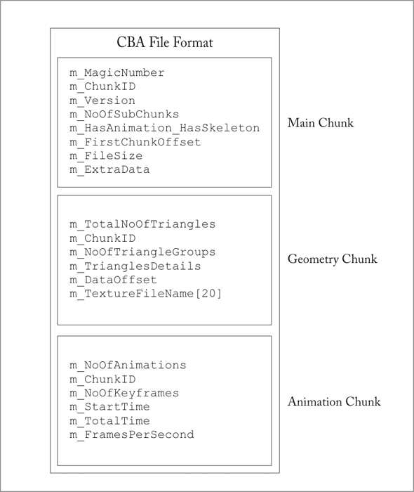
The CBA file format header
You can see in figure 1, how the header for CBA file looks.
Figure 1: Header of CBA file
The structure of the header, 96 bytes in total, in source code is as follows
class CCBAHeader
{
public:
// CBA Main Chunk contains information about all other chunks (32 Bytes in Total)
class CCBAMainChunk
{
public:
unsigned int m_MagicNumber; // Always CBA0
unsigned int m_ChunkID; // Must be 0
unsigned int m_Version; // Version initial 1, In this version only supports GeometryChunk
unsigned int m_NoOfSubChunks; // Total Number of Chunks
unsigned int m_HasAnimation_HasSkeleton; // LowBytes = Animation, HighBytes = Skeleton
unsigned int m_FirstChunkOffset; // From where does the First Chunk Starts
unsigned int m_FileSize; // Total number of Bytes in the File
unsigned int m_ExtraData; // Can be any number of Bytes after this bytes
};
// Contains the Bind Position Geometry Data in CBA (40 Bytes in Total)
class CCBAGeometryChunk
{
public:
unsigned int m_TotalNoOfTriangles; // Total Triangles
unsigned int m_ChunkID; // Must be 1
unsigned int m_NoOfTriangleGroups; // Number of Triangle Groups Categorized by Material
unsigned int m_TrianglesDetails; // 1 = Only Vertices, 2 = Vertices + Normals, 3 = Vertices + Normals + TextureCoords
unsigned int m_DataOffset; // Actual Data Starts from this Offset
char m_TextureFileName[20]; // Texture files name (.jpg,.png,.tga,.bmp)
};
// Contains the Animation Data in CBA (24 Bytes in Total)
class CCBAAnimationChunk
{
public:
unsigned int m_NoOfAnimations; // Total Animations Keyframes
unsigned int m_ChunkID; // Always 2
unsigned int m_NoOfKeyframes; // Total Animations Keyframes
float m_StartTime; // Start Time of the animation
float m_TotalTime; // End time or total time of the animation
float m_FramesPerSecond; // Frames Per second to render
};
private:
CCBAMainChunk m_MainChunk; // The Main Chunk of CBA file
CCBAGeometryChunk m_GeometryChunk; // The Geometry Chunk of CBA file
CCBAAnimationChunk m_AnimationChunk; // The Animation Chunk of CBA file
};
Immediately, after the header is finished, the actual data of the CBA file format starts.
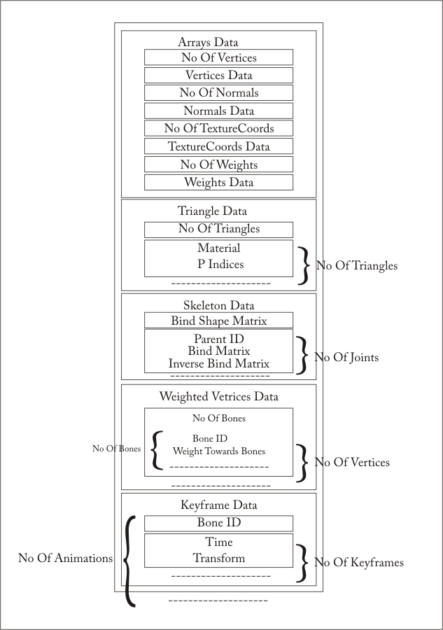
Figure 2: Data section of CBA file
As you can see the data section of the CBA file format is very simple. The first four elements are the 4 arrays we need which are saved in index form.
First one is the Vertices data, which says number of vertices in a 4 byte integer, and the actual data in 4 byte floats array.
Second one is the Normals data, which says number of Normals in a 4 byte integer, and the actual data in 4 byte floats array.
Third one is the Texture Coordinates data, which says number of Texture Coordinates in a 4 byte integer, and the actual data in 4 byte floats array.
Fourth one is the Vertex weights data, which says number of Vertex Weights in a 4 byte integer, and the actual data in 4 byte floats array.
After that we have the triangle group's data, we already know how many triangle groups we have from the header so for each triangle group we save its number of triangles in a 4 bytes unsigned integer and second we save its material which is 4, 4 component vectors and 2 floats. In total 72 bytes for material. After that we save the triangles indices for each triangle, which are 3 unsigned shorts (1 for each vertex) per each attribute. So for a triangle which specifies Vertex, Normal and Texture Coordinate, we save 3 * 3 = 9 indices.
After the triangles data we write the Skeleton data, first we write the bind shape matrix for the skeleton. Then for each Joint we write its Parent ID, Joint Matrix, (which is called Bind matrix in the figure) and its inverse bind matrix. Remember we are not writing the Bone ID itself, in the skeleton, which can be considered as the number/index of the bone we read, so the first bone we read gets an ID of 0, the second one gets an ID of 1 and so on.
After the skeleton we have the weighted vertices data. For each vertex from the vertices source in the Geometry data section, we have to specify its weight towards any bone. So for each vertex we write the number of bones affecting this vertex, and then for each bone affecting this vertex, we write the Joint ID/Bone ID and the weight towards that bone.
And at the end we write the Animations key frame data. As you might have noticed that the animation nodes are targeting Joints from the skeleton and this was one of our assumptions that only skeletal animation is supported and not backed animations or vertex animation. So for each Bone/Joint targeted by the animations from the library animations we write it's Bone ID and then its number of key frames, which consists of "time" and a Joint Matrix, which is called "transform" in the figure.
And that’s the whole CBA file format. In the next part you will learn how to create this Character in OpenGL scene that we saved in CBA files, how to connect it to the skeleton and how to animate it.
Part 2.2:
Implementation part; skeletal animation in C++ using OpenGL
Implementation of Skeletal Animation in C++
At last we are here :) for which we were waiting. This part of the tutorials is the most important of all the other parts we have read so far. We will first try to write the implementation for loading the CBA file that we wrote before in C#. You can also download this CBA loading API from downloads section of this website.
The API has a CCBA class which handles loading and displaying of the CBA files, which looks like follows.
class CCBA
{
public:
CCBA(void);
~CCBA(void);
// Some of the Functions are excluded from this text for the sake of simplicity
void Draw();
bool Update(unsigned long a_MiliSeconds);
void SetupSkeleton(int a_Frame);
void SetupBindPose();
void ReadCBA(string a_FileName);
protected:
void ReadHeader(CExport *a_File, string a_FileName);
void ReadArray(CExport *a_File, float **a_Destination,unsigned int &a_Size);
void ReadTriangles(CExport *a_File);
void ReadSkeleton(CExport *a_File);
void ReadAnimations(CExport *a_File);
void WriteCBA(string a_FileName);
void CalculateBound();
void ConvertToArrays();
private:
// Only the most important member variables are shown here
CCBAHeader *m_Header; // Header (Contains information about the file)
CGeometryData *m_GeometryData; // Common data in the Mesh (List of Vertices/Normals/TexCoords)
CSkeletonData *m_SkeletonData; // Skeleton Data used for animation
Vector<CTriangleGroup*> *m_TrianglesGroups; // Individual Triangle Groups Separated By Material Data (Just Indices and Material)
};
In the CCBA class the most important member variables are m_Header, m_GeometryData, m_SkeletonData and m_TriangleGroups the rest of the stuff is provided for the sake of completeness. As the names suggests, m_Header contains the Header, m_GeometryData will contain the Geometry of the Character, m_SkeletonData will contain the Joints Hierarchy, and m_TriangleGroups contains all the Triangle groups which are separated by Material, by the COLLADA Exporter from StudioMax.
The ReadCBA function of CCBA class looks like this.
void CCBA::ReadCBA( string a_FileName )
{
CExport *File = new CExport(0,a_FileName);
this->ReadHeader(File, a_FileName); // Read Header
this->ReadArray(File, &this->m_GeometryData->m_VerticesArray, this->m_GeometryData->m_VerticesArraySize); // Read Points
this->ReadArray(File, &this->m_GeometryData->m_NormalsArray, this->m_GeometryData->m_NormalsArraySize); // Read Normal
this->ReadArray(File, &this->m_GeometryData->m_TextureCoordsArray, this->m_GeometryData->m_TextureCoordsArraySize); // Read Texture Coordinates
if (65536 & this->m_Header->m_MainChunk.m_HasAnimation_HasSkeleton)
this->ReadArray(File, &this->m_GeometryData->m_VertexWeightsArray, this->m_GeometryData->m_VertexWeightsArraySize);// Read Weights Data
this->ReadTriangles(File); // Read Triangles Data
if (65536 & this->m_Header->m_MainChunk.m_HasAnimation_HasSkeleton)
{
this->ReadSkeleton(File); // Read Skeleton Data
this->ReadAnimations(File); // Read Animations Data
this->SetupInverseBindAttributes(); // Extra Processing for setting up for Skinning
}
delete File;
this->ReadClipsInformation(a_FileName); // Read Animation Clips
this->CalculateBound(); // Calculates Bounding Sphere
if (this->m_Header->m_MainChunk.m_Version == 1) // CBA Version 1 is changed to 2
{
this->ConvertToArrays();
this->WriteCBA(a_FileName);
this->DuplicateSkinnedData();
}
else
this->DuplicateBackupData();
this->FillVertexBufferObject(); // Makes it Ready to be rendered
this->FillIndexBufferObject(); // Makes it Ready to be rendered
this->SetupTexture(); // Sets up Texture and loads
}
You can see that the function is quite simple; it’s just reading the sections that we discussed before. For example it reads header, and all arrays, and then reads Triangles etc. One thing that I would like to explain here is that the exporter that we discussed before write a CBA version 1.0, which means all the data is saved as it is as we read from COLLADA. In ReadCBA function we check if the CBA version is 1.0 then we convert it to CBA Version 2.0. And before doing that, ConvertToArrays() is called, which takes all the arrays from CBA and makes them ready to be used with OpenGL Vertex Buffers and Index Buffers. The Difference between these two types is that, for example we have one triangle in COLLADA and it has 3 Attributes per vertex. So each vertex of a triangle in COLLADA has 1 Index per Attribute, and 3 indices for 3 attributes. While OpenGL Vertex Buffers can only read One Index per vertex for any number of attributes. For that purpose we have to do some extra processing on the data arrays to shuffle them so that each vertex used in a triangle has same Index for all its attributes from the attributes sources. And then we resave this new CBA file as Version 2.0. If you don’t understand this process, then don’t worry and keep on reading because you need this step only if you want to render the mesh using OpenGL vertex and index buffers. If you want to render everything in immediate mode then you don’t have to worry about that.
The rest of the functions are self explanatory, each one of them reads the corresponding section from CBA files, and if I try to explain each and every one of them separately it will easily get very boring.
The main purpose of ReadCBA is to read the CBA file and fill the data structures that we created for saving the Character data. We have already discussed the header structure of CBA file. Now we will discuss the rest of the data structures that we save.
CGeometryData *m_GeometryData; // Common data in the Mesh (List of Vertices/Normals/TexCoords)
CGeometryData class contains all the Data that we need for the Character other then Skeleton and Animations data. And it looks like follows.
class CGeometryData
{
public:
CGeometryData(void);
~CGeometryData(void);
//Functions for this class are removed
private:
float *m_VerticesArray; // All the Vertices
float *m_SkinnedVerticesArray; // All the Skinned Vertices
float *m_NormalsArray; // All the Normals
float *m_SkinnedNormalsArray; // All the Skinned Normals
float *m_TextureCoordsArray; // All the Texture Coordinates
float *m_VertexWeightsArray; // All the Vertex Weights
Vector<CVertexInfluence*> *m_VertexInfluences; // Vertices Influences
unsigned int m_VerticesArraySize;
unsigned int m_NormalsArraySize;
unsigned int m_TextureCoordsArraySize;
unsigned int m_VertexWeightsArraySize;
};
We will read all the Vertices, Normals, Texture coordinates and Vertex Weights arrays in this m_GeometryData pointer. If you see we also have Duplicated copies of both the Vertices array and Normals array. These copies are used during skinning and will be explained later. Since the Vertex Texture coordinates and vertex weights never change during skinning, we don’t need copies of them.
Apart from all that, we have a list of CVertexInfluence pointers for each model. This is the list where we save the data regarding which bone is influencing which vertex with how much weight. The structure of CVertexInfluence is as follows.
class CVertexInfluence
{
public:
CVertexInfluence(void);
~CVertexInfluence(void);
private:
unsigned int m_NoOfInfluences; // Total Number of Influences
unsigned int *m_Weights; // Weights Array
int *m_Joints; // Joints Array
};
The next thing in CCBA is;
CSkeletonData *m_SkeletonData; // Skeleton Data used for animation
This is where the skeleton data is saved and the structure of the CSkeletonData is as follows.
class CSkeletonData
{
public:
CSkeletonData(void);
~CSkeletonData(void);
private:
unsigned int m_NoOfBones; // Total Number of Joints in Skeleton
unsigned int m_NoOfKeyframes; // Another Copy of the No Of Key frames of animation
CMatrix4f *m_BindShapeMatrix; // Bind Shape Matrix
CBone **m_Bones; // All the bones
CBone *m_RootBone; // Root bone reference to one of the Bone in the m_Bones
};
Here we save all the bones and the bones contain the hierarchy information. We have the Bind Shape Matrix, and a bone count. How each bone is structures is as follows.
class CBone
{
public:
CBone(void);
~CBone(void);
private:
int m_ID; // ID of this bone
int m_ParentID; // Parent ID of this bone
CMatrix4f *m_JointMatrix; // The Bind Pose Matrix
CMatrix4f *m_InverseBindMatrix; // The Inverse Bind Pose Matrix
CMatrix4f *m_WorldMatrix; // The World Matrix
CMatrix4f *m_SkinningMatrix // The Matrix Used for calculations
unsigned int m_ChildCount; // Number of Children
Vector<int> *m_Children; // Children of this bone
unsigned int m_NoOfKeyframes; // No Of key frames of animation for this bone
CKeyframe **m_Keyframes; // All Key frames for this Bone’s animation
};
Here we have the Bone ID, Parent Bone ID, Joint Matrix, Inverse Bind Matrix, all the Child bone IDs and all the key frames for this bone. World Matrix and Skinning Matrix are created and changed at run time when we run the animation, so they are just convenience buffers. Each key frame is a pair of Transformation (Joint Matrix) and time.
class CKeyframe
{
public:
CKeyframe(void);
~CKeyframe(void);
private:
float m_Time; // Time of this key frame
CMatrix4f *m_Transform; // Transformation of this Key frame
};
The next very important thing in CCBA is;
Vector<CTriangleGroup*> *m_TrianglesGroups;// Individual Triangle Groups Separated By Material Data (Just Indices and Material)
The Structure of a CTriangleGroup is as follows.
class CTriangleGroup
{
public:
CTriangleGroup(void);
~CTriangleGroup(void);
// The functions for this class are removed
private:
CTriangle *m_Triangles;
CMaterial *m_Material;
unsigned int m_NoOfTriangles;
};
This class is used for saving the triangles data from CBA file as well as the material information for each triangle group. For the sake of completeness the structure of CTriangle is also presented, which is used to save 9 indices for 3 vertices and their 3 attributes of each vertex of a triangle.
class CTriangle
{
public:
CTriangle(void);
~CTriangle(void);
// The functions for this class are removed
private:
unsigned short m_VerticesIndex[3];
unsigned short m_NormalsIndex[3];
unsigned short m_TexturesIndex[3];
};
And that’s all the data structures that we need to read the Character in. Now all what we have to do is to, use this data and make our character animate. Which is done half in setting up the skeleton SetupSkeleton() and half in SetupBindPose().
How skeletal Animation works?
If you have come so far you might already know that so far we have saved data for the character in 3 Categories, one category is the Geometry data of the Character which is saved in m_GeometryData and m_TriangleGroups, second category is the skeleton data, which is saved in m_SkeletonData, and the Third Category is the animation data which is saved within the bones inside the m_SkeletonData. The first category of Geometry data can be used alone to draw the character on screen. The pose that you will see is called the Modeling pose, in which the character was modeled. Please refer to the following figure.
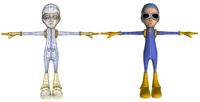
Figure 3: Modeling Pose of a Character
All you have to do to draw this Pose is to render all the triangles from all the triangle groups (m_TriangleGroups) with texture applied.
The second category can be used to draw the skeleton in Bind Pose, which is the pose when the skeleton was attached to the skin.
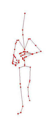
Figure 4: Skeleton in Bind Pose
You can see in this here that the skeleton is ready to be used to transform the vertices of the Modeling pose to bring the Character in this pose. The process goes like this.
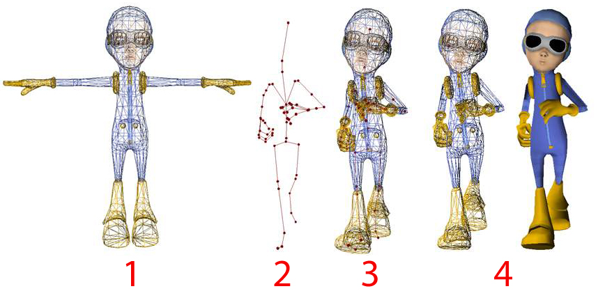
Figure 5: Process of Binding Skeleton to the Skin
The model is given to us in Modeling Pose Just like shown in Figure 5.1, we have also setup the skeleton in the Bind pose like shown in Figure 5.2, we need to transform all the vertices of the model in Figure 5.1 using the skeleton from Figure 5.2 to get the shape of Figure 5.3, this is done with the Skinning equation given later in the text, and then we render the model using textures and materials as shown in Figure 5.4.
The transformation for each bone is calculated by multiplying its Joint Matrix with the parent Bone’s World matrix. An example is given in the following figure.
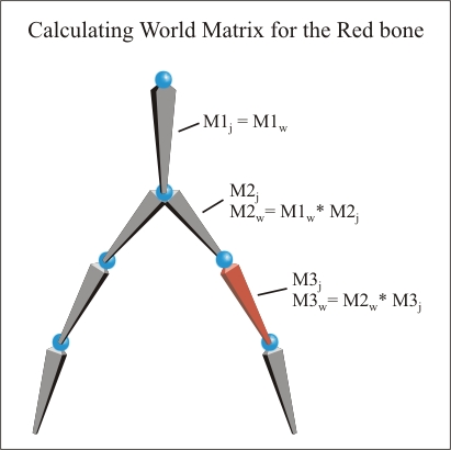
Figure 6: Deriving the skeleton world matrices
In this figure the World matrix for the red bone is calculated. We always start from the root bone, since the root bone doesn’t have any parent; its world matrix becomes its joint matrix. Next we pick the next bone in the hierarchy, we get its world matrix from multiplication of the parent bone’s (root bone) world matrix (M1W) with this bone’s Joint Matrix (M2j), and this world matrix is called M2W in the figure. Now we move to the next bone (red bone) and to calculate its world matrix we multiply its parent bone’s World matrix (M2W) with the red bone’s Joint matrix (M3j) and we get the Red bone’s World Matrix called (M3W). This process is repeated for each bone, taking its parent bone world matrix and multiplying its own join matrix with it, and then saving the result in its own world matrix. As you can see this process must be started from the root bone, so that we don’t have dirty world matrices while we go down.
In this model most of the vertices are influenced by more then one bone, and the influence is denoted by the weight associated with each vertex toward each bone that influences it. Without this the animation looks very rigid. Example of vertices affected by only one bone is given as follows.
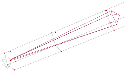
Figure 7: Vertices only effected by one bone
Example of vertices affected by more then one bone is given as follows.
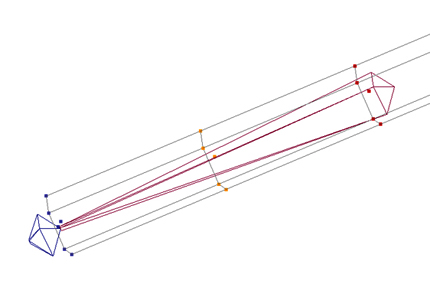
Figure 8: Vertices effected by more then one bone
In the following figure you can see how the vertex weights are distributed over the vertices. Red Color vertices means high influence from the red bone, while blue color means less influence from the selected Bone (red bone), the colors in between red and blue are used for weight values between zero and one.
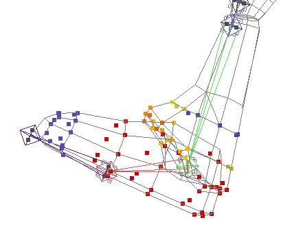
Figure 9: Vertices affected with different weights by the red bone
In the following sections you will see how the weights of each bone affecting a vertex are accumulated to get the final vertex position.
And the Final and Third category is the Animations data. We use the animation data to move the Skeleton of the character in different poses and then use that new pose generated by the animation data to transform the vertices of the character and draw in new pose. So all what the animation data do is to animate the skeleton and we use the animated skeleton to animate our character.
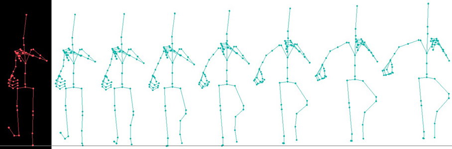
Figure 10: Animation data is applied to the skeleton to animate the skeleton
Here we can see that the Bind pose skeleton is transformed by different key frame transforms from the animation data, to define different poses. And then these poses are used to drive the skin, and transform the vertices of the character.
This was all the theory behind skeletal animation, how it is done using our CBA file data is given in the following sections.
In SetupSkeleton() we make the skeleton ready for next pose, the body of the function is as follows. And then we use that pose to setup our vertices in the new pose which is done in SetupBindPose().
void CCBA::SetupSkeleton(int a_Frame)
{
// Update the tree of bones
static CStack<int> BonesStack;
BonesStack.Push(this->m_SkeletonData->m_RootBone->m_ID);
while (!BonesStack.Empty())
{
unsigned int CurrentBone = BonesStack.Pop();
assert(CurrentBone != -1 && "Current Bone is Null");
CMatrix4f WorldMatrix = *this->m_SkeletonData->m_Bones[CurrentBone]->m_JointMatrix;
if (this->m_SkeletonData->m_Bones[CurrentBone]->m_NoOfKeyframes > 0/* && frame > 0*/)
{
assert(a_Frame < (int)this->m_SkeletonData->m_Bones[CurrentBone]->m_NoOfKeyframes && "Invalid Key frame");
float InBetween = (float)(this->m_AnimationTime * (float)this->m_SkeletonData->m_NoOfKeyframes / this->m_Header->m_AnimationChunk.m_TotalTime);
InBetween -= a_Frame;
if (a_Frame < (int)this->m_SkeletonData->m_Bones[CurrentBone]->m_NoOfKeyframes - 1)
{
WorldMatrix = Interpolate(*this->m_SkeletonData->m_Bones[CurrentBone]->m_Keyframes[a_Frame]->m_Transform,
*this->m_SkeletonData->m_Bones[CurrentBone]->m_Keyframes[a_Frame + 1]->m_Transform,InBetween);
}
else
WorldMatrix = *this->m_SkeletonData->m_Bones[CurrentBone]->m_Keyframes[a_Frame]->m_Transform;
}
if (this->m_SkeletonData->m_Bones[CurrentBone]->HasParent())
WorldMatrix = WorldMatrix * *this->m_SkeletonData->m_Bones[this->m_SkeletonData->m_Bones[CurrentBone]->m_ParentID]->m_WorldMatrix;
*this->m_SkeletonData->m_Bones[CurrentBone]->m_WorldMatrix = WorldMatrix;
*this->m_SkeletonData->m_Bones[CurrentBone]->m_SkinningMatrix = *this->m_SkeletonData->m_Bones[CurrentBone]->m_InverseBindMatrix * WorldMatrix;
// Handle its Children
if (this->m_SkeletonData->m_Bones[CurrentBone]->HasChildren())
{
unsigned int NoOfChildren = this->m_SkeletonData->m_Bones[CurrentBone]->m_ChildCount;
for (unsigned int Index = 0; Index < NoOfChildren; Index++)
{
BonesStack.Push(this->m_SkeletonData->m_Bones[CurrentBone]->GetChildAt(Index));
}
}
} // While
}
In very short and very simple, all this function is doing is to take the current frame Joint Matrix for the current bone and if it’s a root bone then save that Joint matrix as world matrix for the current bone, other wise take the parent bones World matrix and multiply this bone’s Joint matrix with it and then save the result as current bone’s World Matrix. We have to start this process from the Root bone so that we don’t have dirty world matrices from previous frames in the tree. This is why a Depth first Tree Traversal is used, using a Stack. Now for each bone we have a new World Matrix for the current frame of animation. And in the same function we use this World Matrix to derive the skinning matrix for the current bone, which is used in SetupBindPose() to do the skinning, which means to attach all the vertices with the skeleton and move them with the corresponding bones. If you see SetupBindPose() you will see in the beginning the skinning calculation equation. In that equation we need have (IBMi * JMi) which means we need to multiply a bone’s Inverse Bind matrix with its World matrix so that’s what is done in SetupSkeleton() and the result is saved in advance in m_SkinningMatrix for each bone, with this we don’t have to do this multiplication for each and every vertex we need to skin to the skeleton. One other thing which we can do before hand is the (v * BSM) which is the multiplication of each vertex with the Bind Shape matrix of the skeleton. So we do that once and then use the updated vertices. The actual skinning is done in the following function.
void CCBA::SetupBindPose()
{
/*
The skinning calculation for each vertex v in a bind shape is
for i to n
v += {[(v * BSM) * IBMi * JMi] * JW}
• n: The number of joints that influence vertex v
• BSM: Bind-shape matrix
• IBMi: Inverse bind-pose matrix of joint i
• JMi: Transformation matrix of joint i
• JW: Weight of the influence of joint i on vertex v
I have Got (v * BSM) and (IBMi * JMi) already multiplied since they are constants
*/
rUsInt NumberOfVertices = this->m_GeometryData->m_VerticesArraySize / 3;
for (rUsInt CurrentVertex = 0; CurrentVertex < NumberOfVertices; CurrentVertex++)
{
CVector3f TempVertex;
CVector3f TempNormal;
CVector3f TempNormalTransform;
CVector3f Vertex( this->m_GeometryData->m_VerticesArray[(CurrentVertex * 3) ],
this->m_GeometryData->m_VerticesArray[(CurrentVertex * 3) + 1],
this->m_GeometryData->m_VerticesArray[(CurrentVertex * 3) + 2]);
CVector3f Normal( this->m_GeometryData->m_NormalsArray[(CurrentVertex * 3) ],
this->m_GeometryData->m_NormalsArray[(CurrentVertex * 3) + 1],
this->m_GeometryData->m_NormalsArray[(CurrentVertex * 3) + 2]);
float TotalJointsWeight = 0;
float NormalizedWeight = 0;
for (rUsInt CurrentInfluence = 0; CurrentInfluence < (*this->m_GeometryData->m_VertexInfluences)[CurrentVertex]->m_NoOfInfluences; CurrentInfluence++)
{
TempVertex += ((Vertex *
*this->m_SkeletonData->m_Bones[(*this->m_GeometryData->m_VertexInfluences)[CurrentVertex]->m_Joints[CurrentInfluence]]->m_SkinningMatrix) *
this->m_GeometryData->m_VertexWeightsArray[(*this->m_GeometryData->m_VertexInfluences)[CurrentVertex]->m_Weights[CurrentInfluence]]);
this->m_SkeletonData->m_Bones[(*this->m_GeometryData->m_VertexInfluences)[CurrentVertex]->m_Joints[CurrentInfluence]]->m_SkinningMatrix->RotateVector(Normal,TempNormalTransform);
TempNormal += TempNormalTransform * this->m_GeometryData->m_VertexWeightsArray[(*this->m_GeometryData->m_VertexInfluences)[CurrentVertex]->m_Weights[CurrentInfluence]];
TotalJointsWeight += this->m_GeometryData->m_VertexWeightsArray[(*this->m_GeometryData->m_VertexInfluences)[CurrentVertex]->m_Weights[CurrentInfluence]];
}
if (TotalJointsWeight != 1.0f)
{
NormalizedWeight = 1.0f / TotalJointsWeight;
TempVertex *= NormalizedWeight;
TempNormal *= NormalizedWeight;
}
this->m_GeometryData->m_SkinnedVerticesArray[(CurrentVertex * 3) ] = TempVertex.x;
this->m_GeometryData->m_SkinnedVerticesArray[(CurrentVertex * 3) + 1] = TempVertex.y;
this->m_GeometryData->m_SkinnedVerticesArray[(CurrentVertex * 3) + 2] = TempVertex.z;
this->m_GeometryData->m_SkinnedNormalsArray[(CurrentVertex * 3) ] = TempNormal.x;
this->m_GeometryData->m_SkinnedNormalsArray[(CurrentVertex * 3) + 1] = TempNormal.y;
this->m_GeometryData->m_SkinnedNormalsArray[(CurrentVertex * 3) + 2] = TempNormal.z;
}
}
If you read the comments in the beginning of the functions it says how the skinning is done on this data that we have read so far.
The skinning calculation for each vertex v in a bind shape is
for i to n
v += {[(v * BSM) * IBMi * JMi] * JW}
• n: The number of joints that influence vertex v
• BSM: Bind-shape matrix
• IBMi: Inverse bind-pose matrix of joint i
• JMi: Transformation matrix of joint i
• JW: Weight of the influence of joint i on vertex v
I have Got (v * BSM) and (IBMi * JMi) already multiplied since they are constants
As we have discussed already I have (v * BSM) and (IBMi * JMi) already multiplied from the SetupSkeleton() function, and we run a lope for all the vertices in the character and get both the current vertex as well as current normal (remember that the normal is also pre-multiplied with Bind Shape Matrix) and we run another nested lope for each bone (influence) influencing this vertex and take its weight and m_SkinningMatrix and multiply them with the current vertex, which is already multiplied with Bind shape matrix, and then save it back in the copy of the Vertices array (m_SkinnedNormalsArray) which we talked about when we created the data structure of CGeometryData. Now if we use this changed vertex and display the character, we will see the character in the current frame’s pose. This is the simple way of doing one frame of skinning for the character, if we want to animate it for the whole animation key frames, we must iterate for all the frames over time and call SetupSkeleton() and SetupBindPose() in that order.
As we discussed before if the time falls in between two key frames then we have to do interpolation on the two transforms for those two key frames. And then use the new value of transform to setup the skeleton. But once you have done the simple form of just running the character on all the key frames only, you can take the next step and do the interpolated animations or smooth animation. For that you might also like to save the transforms in quaternion instead of matrices.
This animation process can get as much complicated as you want it to be, in these implementations that I presented in this set of tutorials you will find the simple most animations you can achieve. You don’t even need to worry about any interpolations and such until you have your character changing pose from one frame to another. Once you have achieved that, you can go for improving your animation system and introduce things like, Smooth animation, Animations Instancing system, blending two animations, Layering two animations and doing Forward Kinematics on your animations etc and it never ends :).
I hope this tutorial will help people in working with COLLADA as well as doing skeletal animations, please don’t hesitate to bust my ass with your constructive comments and criticism. You can always reach me through my email address given in the contact section of the website.
List of Figures
Figure 1: CBAHeader.jpg
Figure 2: CBAData.jpg
Figure 3: ModelingPose.jpg
Figure 4: OnlySkeleton.jpg
Figure 5: Bindpose.jpg
Figure 6: Hierarchy.jpg
Figure 7: Weight0.jpg
Figure 8: Weight1.jpg
Figure 9: Weight2.jpg
Figure 10: Animation.jpg
Tags:
Skinning in COLLADA, Software Skinning, Skeletal Animation System in COLLADA, Skeletal Animation in COLLADA, COLLADA Animation Tutorial, COLLADA Skeletal Animation Tutorial, COLLADA Skeleton Animation Tutorial, Animation Data in COLLADA, Beginning COLLADA Programming, Starting COLLADA, COLLADA for Beginners, Step by Step Programming COLLADA, Reading COLLADA documents Step by Step, Exporting COLLADA documents, Importing Data from COLLADA, Importing Skeleton from COLLADA, Importing Exporting COLLADA documents in C++, COLLADA DOM, Feelings Software, COLLADA Conditioners, Working with COLLADA in C++, Simple Animation in COLLADA. COLLADA Step by Step Tutorial, Learn COLLADA in days, Skeletal Animation in OpenGL, Reading COLLADA documents in C++ Using OpenGL, Reading COLLADA documents Step by Step in OpenGL, COLLADA documents in DirectX, Character Animations in COLLADA, Step by Step Character Animations using COLLADA. Step by Step Character animation Tutorial using C++