Step by Step Skeletal Animation in C++ and OpenGL, Using COLLADA PART 1
Level: Beginner to Intermediate
Introduction: Hi I am waZim and welcome to my first tutorial(s) on Skeletal Animation. This series of tutorials consists of two parts.
1) Reading and Understanding COLLADA. (high level overview of COLLADA documents)
2) Actual Implementations in C++ using OpenGL, of what we learn in Part 1.
These two parts are further broken down into sub categories or parts which will be explained as we progress through the tutorials.
Who should read these tutorials?
This tutorial is written for those programmers (Not artists) who want to implement Skeletal Animations in General and Skeletal Animations using COLLADA in Specific, Using C++ and OpenGL, in their (Game) Engines. It is also helpful to programmers who want to learn how to load static 3D COLLADA models in their engines;
What we will and will not cover?
In this set of tutorials I will try to explain step by step how to read Geometry, Skeleton and Animation Data from COLLADA documents and how to implement and animate your characters using skeletal animations, in C++ and OpenGL. We will not be covering EVERY aspect of COLLADA; rather we will take some assumptions which will help us to understand the COLLADA document format easily.
We will also not discuss things like shaders and FX using COLLADA.
What you need to know, to get the Most out of these tutorials?
Any-one who wants to get the most benefit out of these tutorials should have solid knowledge of programming in general and C++ programming in particular. Advanced OpenGL programming is not required although it is a plus. You should know what a vector is and what a texture coordinate is, how geometry and animation is represented, what an XML format is and so on. For the rest, I hope you will learn everything you need here.
What you need to have, to learn and read through these tutorials?
You need a C++ compiler with OpenGL Support and working drivers for OpenGL.
Some COLLADA example documents. Which you can find on www.COLLADA.org , find model bank, or in downloads section of this website (www.wazim.com).
A good Text Editor like Notepad++
Background and Motivation:
Over the years when I first started graphics programming, I was already tired of writing geometry by hand and drawing everything vertex by vertex :). Then the time came when I saw some simple demos over the internet, reading Geometry data from ASCII files in OpenGL, like .OBJ file format etc.. After some time, I wanted to animate the models so I found MD2 Demos. When I started creating my own MD2 files, it was really hard to find a robust importer for MD2 files for my own engine. In the end, I decided to forget about all those formats and read Autodesk Maya (.ma) or Autodesk Studio Max (.max) files. But reading Geometry and animation data from those two files are not recommended by the authors of those two Authoring softwares. I don’t know much about Maya .mb or .ma files but I love Studio Max and .max files and yet they are unfortunately poorly documented. And even if you start to write an exporter for any of these files it’s really hard to port your models from Maya to Max or vice versa. There is always something missing when you import those files into other software.
The solution that I found was COLLADA. COLLADA documents are cross platform because they are stored in UTF-8 format using XML schema. I think you already know something about COLLADA that is why you are here! So let’s not waste any time and jump straight to the implementation. If you want to read more about COLLADA documents then go visit (www.COLLADA.org) and keep reading the COLLADA wiki and COLLADA forums.
So after I have found COLLADA the solution to my problems I have been working with COLLADA. There are many implementations of COLLADA which are too generic, for example the first thing I saw was the COLLADA DOM which is available on COLLADA.org. And you can write your own code on top of DOM to extract all the information from COLLADA document which is loaded in DOM and export it to your Custom Format. This is the easy way to go but still you need to understand the COLLADA format and then DOM has its own problems. You might find it very hard to get what you really need and what you don’t need. What I found annoying with DOM was that it can read Texture Coordinates with (s,t) two components while can’t read (s,t,p) type of Texture coordinates which are default to Studio Max COLLADA Exporter. So at the end I decided to write my own exporter and it’s really not that hard as it seems.
When I started reading about COLLADA I was unable to find a step by step tutorial, so the purpose of this tutorial is to give you the COLLADA document format in easy to learn chunks and C++ code to implement, with step by step explanation.
Part 1:
Reading and Understanding COLLADA documents
As we have discussed in the introduction part, this tutorial is split in to two parts, first one general introduction to COLLADA documents which is irrespective of any programming language. So if you want to skip this part and directly jump to the implementation part, it is quite possible that you will find it hard to understand what is going on. So it’s highly recommended, for those who know nothing or very little about COLLADA documents, to read this part before moving to the next part.
Enough Ranting :), let’s start working.
COLLADA documents
Before we dig into COLLADA documents I would like you to download the example file which we will be using through out the tutorial. It’s available in the COLLADA Model Bank and is also shipped with COLLADA DOM. It’s called “astroBoy_walk.dae” if you can’t find this file anywhere then its available in downloads section of this tutorial’s website, and you can find it there.
Like we discussed earlier (in case you read the intro part) COLLADA documents are stored in XML format. If you open astroBoy_walk.dae, which I will call example file from now on, in your favorite text editor, you can see a root node called “COLLADA” and if your text editor supports expanding or collapsing XML nodes (if you are using Notepad++ you can set the language type to XML from the “language” menu to get XML Editing enabled) then you can click on the (-) sign in front of <COLLADA> tag to Collapse it to one line, there you will see that the whole file is Collapsed to one line and that’s all the COLLADA document is about.
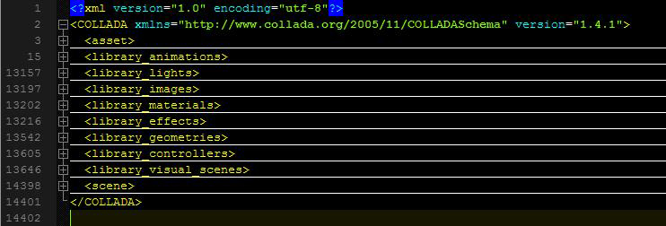
Within this <COLLADA> node which is the root of this .dae or .xml file, you will find many other libraries which are used for storing different types of information like <library_geometries> is used to store geometry data and <library_lights> is used to store Lights in the scene. Refer to figure 1. See it’s not rocket science 🙂 and then within those libraries you will find the actual data. For example a geometry library will have <geometry> nodes and a lights library can have <light> nodes, which means those libraries are used to store more then one lights or geometries in your scene. Now let’s analyze all of those libraries one by one by increasing importance to the tutorial and our COLLADA exporter, in their corresponding sections.
First of all let’s make things easier for us. Just like I said in the beginning we will not be discussing COLLADA documents from all aspects; rather we will be taking some assumptions, to remove complexities.
List of Assumptions:
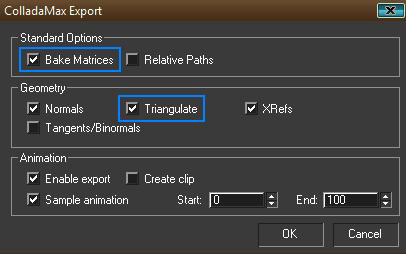
1) Although COLLADA documents exported from Max or Maya Should be the same but in some cases they are different. We will only talk about COLLADA document exported from Studio Max, which of course does not mean that this tutorial might not help those who work in Maya. Because I am still positive that COLLADA documents exported from Maya should be the same, if we export them with backed matrices and triangulate options checked, from the COLLADA Exporter Options dialog. But I have never worked with Maya and don’t know where my exporter might fail.
2) The COLLADA document must have at least and at most a mesh, which means, anything in the asset’s Max file, should be attached. So we must not have more then one <mesh> in the <library_geometries> in the COLLADA document. If we are able to read one <mesh> then we can read a 10000 too.
3) Geometry in COLLADA should be triangulated, since that’s the better (If not best) option, we can provide OpenGL, so we let the triangulation work done by Max.
4) Later in the implementations part we will assume our Model which was exported to COLLADA document has only One Texture file.
5) Animations in COLLADA must have at least or at most one Skeleton, with only one Root Bone (Typical). And I think that’s why we are here, to implement skeletal animation.
6) Animation exported to COLLADA must be baked in matrices, which essentially in some cases makes 1 channel of animation and in others 16 channels of animation (Now what is channel? It should be explained later).
7) Animations can only be valid if the channel targets the “Transform” of the targeted entity, just to keep things clear and easy. When you will bake matrices, then you will have this automatically, so don’t need to worry about that.
8) Animations can’t have nested animations.
9) Only Skeletal Animation is supported (No baked animation yet).
10) Every bone in the hierarchy must be attached as effecter on the skin. In other words, it must be added to the skin.
Keeping those assumptions in mind all the times, let’s start explaining different libraries in their related sections. You might also find it easy and handy to switch to Implementation part for each section immediately, when you read that section, before you finish reading the first part completely. The link to the implementation of each section is given at the end of that section.
Reading Geometry Data from COLLADA document
<library_geometries>
This is by far the most important library of all of the COLLADA libraries; if you have a character to animate we need its geometric data, which is provided in <library_geometries>.
This library contains <geometry> type nodes which contain separate geometries in the scene, keep in mind COLLADA is not just an asset file format rather you can put a complete scene and many scenes in them. Like we assumed we are only concerned with one <geometry> node which will have one <mesh> node. So if so far you have found that node lets analyze it.
<mesh>
Mesh is the node where we will find our geometry data. If you try to analyze the node you will see further at least 1 or 2 <source> nodes, which, depending on its type, gives information about Vertices, Normals and Texture Coordinates etc. In the example file (if you have downloaded from COLLADA.org, it will not have backed animation in it, so you have to import it in Max and then export it back with Backed Matrices and “triangulate” checkbox checked as shown in figure 2), you will find 3 <source> nodes and we are lucky that each source node is defined in the same way in COLLADA.
<souce>
Remember all these XML nodes discussed so far have an ID associated with them which is used for locating the Node in COLLADA document when referred from any place. And Source Nodes are not any exception to that. Now <source> can have many children nodes but the most important ones are <float_array> or <NAME_array> and <technique_common>.
As the names suggests <float_array> contains floats which can be used for different purposes which are described by <technique_common> of that source and the difference between <float_array> and <NAME_array> is that, the former contains floats and the later contains strings.
Now we use the <technique_common>’s <accessor> child node to specify what kind of data is in those arrays <float_array>, <NAME_array> or any other type of many types of arrays. <accessor> node has a “source” attribute which says “What kind of “array” are we talking about?”. And a “count” attribute says how many elements we have in the “array”. The “stride” attribute says after how many values the next element starts.
I hope I am not talking Chinese but let’s explain it with a figure and example COLLADA source.
<source id="vertices_source" name="Vertices">

<float_array id="values" count="6"> 0.3 0.5 0.7 0.2 0.4 0.6 </float_array>

<technique_common>

<accessor source="#values" count="2" stride="3">

<param name="X" type="float"/>

<param name="Y" type="float"/>

<param name="Z" type="float"/>

</accessor>

</technique_common>

</source>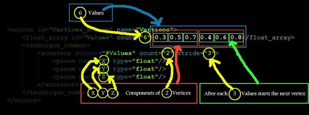
As you can see in figure 3, there are float array’s (count=”6″) values which are 3 (x, y, z) float components of <accessor>’s (count=”2″) number of vertices. And when we have 3 <param> child nodes in <accessor> then we have 3 (x, y, z) components in each Vertex (3D vertex) (it can also be 3 Components of Normal, or 3 Components of Texture Coordinates). This information is very important since I can’t find it in COLLADA Specifications and it took me a lot of time to understand this concept (may be I am dumb) 🙁 So if you don’t understand, please read again.
In short, this source says, “I have 2 vertices with 3 components each, which are saved in <floats_array> as 6 float values”. Components are called “X”, “Y” and “Z”. And they are float type values. If we had a <source> which saves texture coordinates, then those components would be “S”, “T” and “P”.
So that’s all a source is about. Now as we discussed before there are 3 <source> nodes in the example COLLADA document. And as you might have guessed already, the other two sources are for Normals and Texture Coordinates, if you have exported your Model with other attributes then you will have more <source> nodes, like bitangents and tangets etc.
Now when we are able to decode <source>s, we still can’t just decide on the order of those sources which one is Vertices and which one is Normals etc. we have to read one other child of <mesh> which is called <vertices> to find the vertices source, although I really don’t understand the reason why they do this in COLLADA but for the sake of completeness you have to read this Node it has at least one Child node called <input> with a semantic attribute of “POSITIONS” value, which references the vertices <source> with another source name/id. And then you refer to this ID when ever you need the vertices source. If you don’t understand these sections then skip to the next section and you hopefully will understand.
<triangles>
Now as we have assumed we are only considering COLLADA documents triangulated so you will only see <triangles> types nodes as children of <mesh> otherwise you might see <polylist> etc nodes, which we are least concerned with.
This <triangles> node tells all the information we need to make a triangle out of those 3 sources (in this case) which we read earlier. A <triangles> node says how many triangles we have in this <triangles> node with a “count” attribute and also lists “material” attribute which is used to find the material from the <library_material> and that material is used to render the list of triangles from this <triangles> node. So you might see many triangle groups in one Mesh, which are separated by Materials. So we have to read all the <triangles> nodes.
To decode <triangles> nodes we have to read its children in which <input> and <p> are the most important. The number of <input> nodes says the number of attributes per vertex. And <p> has the indices of those attributes in their corresponding <source> nodes. Let’s see an example.
<mesh>

<source id="position"/>

<source id="normal"/>

<source id="textureCoords"/>


<vertices id="verts">

<input semantic="POSITION" source="#position"/>

</vertices>

<triangles count="2" material="Bricks">

<input semantic="VERTEX" source="#verts" offset="0"/>

<input semantic="NORMAL" source="#normal" offset="1"/>

<input semantic="TEXCOORD" source="#textureCoords" offset="2" set="1" />

<p>

0 0 1 3 2 1

0 0 2 1 3 2

</p>

</triangles>

</mesh>
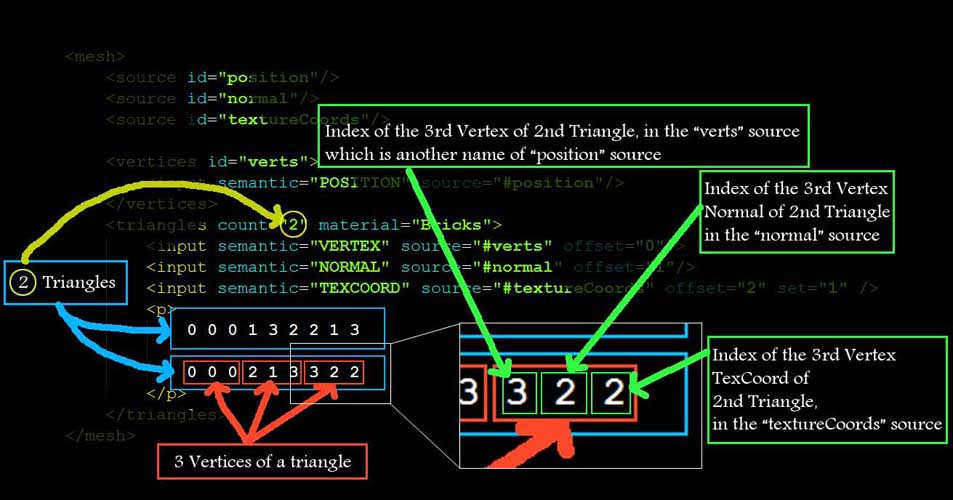
As you can see from the above example <vertices> node is renaming the “position” source with “verts” and then defining the triangles vertices source with “verts” name. So this is why we need to read <vertices> node to find the real position <source> from the <source>s.
If you read the Children of <triangles> node you can see that it has 3 <input> nodes with values of “VERTEX” “NORMAL” and “TEXCOORD” for its semantic attribute. This essentially means that our triangles have 3 attributes per vertex, first Vertex Position, second Vertex Normal and third Vertex Texture Coordinate.
And how we know which one is first in the list of indices in <p>? We can see that
<input> node with semantic = “VERTEX” has offset = “0”,
<input> node with semantic = “NORMAL” has offset = “1” and
<input> node with semantic = “TEXCOORD” has offset = “2”.
So when ever we will read values from <p> for each triangle’s each vertex,
The first one will be the Index of “VERTEX” Position from the “positions” <source>,
The second one will be the index of the “NORMAL” from the “normal” <source> and
The third one is the index of “TEXCOORD” from the “textureCoords” <source>.
Now one thing I would like to make clear here is, that all these values we read from <p> are “indices” not actual values. And all the data for all the triangles are saved as indexed data to save space in case of repetitions of attributes data. To find the real data we have to refer to the corresponding <source>s and pick the corresponding data at that particular index.
Making Triangles is very easy now. All you have to do is keep on reading 3 * (Number of Input Nodes in <triangles>) values from <p> and read the corresponding attribute values from the corresponding <source>s. If we have only one attribute per vertex for any number of triangles then we will have the following <triangles> Node, with only one <input> child. In this case all you have to do to read the triangle is to keep on reading 3 values from <p> and read the corresponding vertex values from the corresponding “verts” source.
<triangles count="2" material="Bricks">

<input semantic="VERTEX" source="#verts" offset="0"/>

<p>

0 3 2

0 2 1

</p>

</triangles>
One thing we still need to know is the “material” attribute of a <triangles> node. This attribute references the material used from the “library_materials> which will we discuss later in the tutorial.
That’s all for the geometry data. If you understand this part correctly I hope you will have no problems going on from here onwards. Other wise go back and read again until you understand completely. Now if you directly want to jump to the implementation part (part 2) of the tutorial, you should be able to read and display static 3D objects in your engine. And if you want to render them with Materials and texture maps as well as animate them, you will have to keep on reading this part of the tutorial completely.
Click here to go to: Implementation section in Part 2 for this section of Part 1
Reading Texture filename from COLLADA document
As you know we took some assumptions in the beginning, one of which was only one texture file can be used in the COLLADA document. This will make finding the file name very easy.
All we have to do is to read the <library_images> and read the “id” attribute of the “Only” <image> node in it. Usually that will be the file name of the texture file used in COLLADA. But it might not be correct file name, and COLLADA might create that ID different then the file name. So, to correctly read the file name we must read the <init_from> child node of <image> node, which gives the whole path, with file name. For our export purposes I am only interested in the file name, not the whole path, so I will tokenize the full path and save the file name only.
Click here to go to: Implementation section in Part 2 for this section of Part 1
Reading Materials from COLLADA document
We discussed in the section “Reading Geometry Data from COLLADA document” that each triangle group is separated by a “material” and the Material ID is the value of the “material” attribute in <triangles> node. Now to find those materials with those IDs we have to read <library_materials>. In <library_materials> you will find <material> nodes with those IDs which were referenced from <triangles> nodes. But unfortunately those <material> nodes have only one type of child named <instance_effect> which has one attributes called “url”. All what its saying is that this specific <material> node is referring to an effect from the <library_effects>, which in turn defines the material completely.
So we take the value of this “url” attribute for this specific <material> and find it in <library_effects>, now unfortunately this library <library_effects> is the most complicated library of COLLADA as much as I know. It can get very complicated when shaders and what not is included in the COLLADA document. But since I promised to keep things clear and easy, we will only read the data that we desperately need for defining a material.
Once we have found the <effect> node with id of the value of the “url” attribute for any material, we have to find either <phong> or <blin> node in <profile_COMMON> child node of the <effects> node. <phong> or <blin> are usually inside <technique> child node of <profile_COMMON>. Once we have found either <phong> or <blin> keep looking for all the parameters of the Material we are looking for, like “ambient” “diffuse” “specular” “emission” “shininess” and “transparency” etc. what ever you need for the material to look good. Usually “diffuse” “shininess” and “transparency” is enough to create a good looking material.
How can we read the data from those nodes is very easy? Usually ambient, emission, diffuse and specular nodes has 4 float values, inside a <color> child node, which corresponds to “RGBA” components of that particular material’s property, while reflectivity and transparency etc have 1 float value.
<ambient>

<color>1.0 1.0 1.0 1.0</color>

</ambient>


<transparency>

<float>0.5</float>

</transparency>
If we have placed a texture map on the diffuse color of the material then <diffuse> will not have a <color> child, rather that texture image. But for the sake of ease we will not worry about this and assume the texture map is always applied on the <diffuse> component of the material, which means we will not be reading <diffuse> values from COLLADA. But we will be using a default value for diffuse inside our OpenGL implementation.
That’s all what we need for any static geometry. So if you are only interested in reading Static geometry from COLLADA you can stop reading this part and jump to the implementation. Other wise keep on reading for extracting animation data from COLLADA documents.
Click here to go to: Implementation section in Part 2 for this section of Part 1
Reading Skeleton from COLLADA document
We assumed that we will only read COLLADA documents with skeletal animations, and not those with backed animations, so we have to read the skeleton from the COLLADA document. By skeleton, I mean reading the Joints (Bones) information. We also have to read the hierarchy of the Joints. This will tell us, who are the child of whom! And who is the parent of a joint etc. In the following figure all these terminologies are explained. Remember that Bones and Joints are One and the same thing, they are just convenience names, and the data that we read from COLLADA is actually a Joint, a Bone is an imaginary line connecting two Joints.
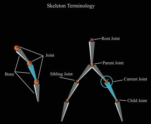
Figure 5: Skeleton Terminologies
In the following figure you can see the skeleton of our example file and the Skin attached to it.
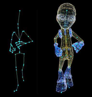
Figure 6: Complete Character in one pose of animation
The red circles on the left in figure 5 are the joints we read from COLLADA and the lines connecting those circles are the imaginary bones, which are used to animate the skin. On the right you can see the skin attached to the skeleton in another frame.
You might remember we took some assumptions, one of which was that, all the joints are added to the skin, which will make your <library_visual_scenes> very simple to read. All you have to do is find the root Joint (bone) <node> of the skeleton in the visual scene and then read the whole tree of joints. One of the disadvantages with this is that you will have a lot of joints considered affecting the skin, but in real they will not have any effect on the skin. And if you don’t add all the bones to the skin, then you will see <node>s of type = “JOINT” and type =”NODE” mixed in the hierarchy. But if you add every bone to skin you will have full tree of type=”JOINT”s only. This is also the default behavior for many engine exporters. When you have <node>s with type=”JOINT” and type=”NODE” mixed in the hierarchy then you have to read <instance_controller> from <library_visual_scenes> and then read <skeleton> each time you have to read a joint. Those <node>s which are not of type=”JOINT” are still Joints but they are not effectors, which means they are not effecting the skin. And that’s why we assumed everything must be attached to the skin, to keep things easy and simple.
To read the hierarchy of the bones, you need to have a data structure which can hold a number of children and a parent of its own kind. (This will get clear in the implementation part). You might also need to save the “SID” attribute of <node>s. Once we have the data structure setup, we will find the root and start reading its children and then their children and so on (recursively) and keep saving them in the data structure. At the end of the whole read process your whole data structure should be able to answer questions like, which joint is the child of whom? And who is the parent of a joint.
Now how can we find the root joint of the skeleton? Since we know we only have one model in the COLLADA document so we don’t have to read the <scene> node to find where the scene is instanced from. We directly go to <library_visual_scenes> and for all the direct (immediate) children of the only <visual_scene> we have to find the <node> who has a children of type <instance_controller>, read the <skeleton> child of this <instance_controller> and that will give you the ID of the root node. Since we have added all the bones to the skin, we will only have one <skeleton> child of <instance_controller>. Now this node is our root of the skeleton and everything connected to this <node> is part of the skeleton.
If you see the structure of this <node> in COLLADA document you will see most of the nodes have <matrix> as the first child. And this <matrix> contains 16 float values, which makes the Joint Matrix of the bone. This is also called the local bone transformation matrix. When we connect all the joints we have to multiply the World Matrix of the parent to the child’s Joint Matrix and save it as world bone transformation matrix for the child. For the root Joint, who doesn’t have a parent, the Joint Matrix becomes the World transformation matrix.
By now you should be able to read the skeleton and derive the bind pose of the skeleton from the Joint matrices you read for each <node>. In the next section we read the skinning information which connects this skeleton with the skin.
Click here to go to: Implementation section in Part 2 for this section of Part 1
Reading Skinning information from COLLADA document
So far we have read the geometry (vertices attributes information, materials, texture filename) as well as skeleton of the model. What we need to know now is how this skeleton is connected to the skin (Geometry). We have read many Joints in the skeleton. But we still don’t know which Joint influence which vertex. Some of the joints might not even influence any vertex at all. But if you remember we took an assumption that all the Joints must be added to the skin. In that case every joint must be influencing the skin theoretically.
To properly connect the skin (geometry) to the skeleton we need skinning information, and this section will try to help you understand, where we can find skinning information in COLLADA?
There is one other thing I would like to explain before we go further. If we have a character who’s each vertex is connected to only one Joint. When ever that Joint moves the vertex connected to it must also move. And you will see very rigid animation. But this is not how things work. Almost every vertex is connected to more then one Joint. And we specify the influence of each joint on that vertex with the help of vertex weights. Each joint influences that particular vertex some percentage of the total influence which totals to 1. So vertex weights are very important part of the skinning information.
<library_controllers>
<library_controllers> contains all the influences (joints) and their connectivity through vertex weights for the whole model. According to our assumptions we only have one mesh and one skeleton. So we will have only one <controller> node in the list of children of <library_controllers>. Once we have found the one and only <controller> node, we have to find its child node <skin>. In the <skin> node, find the <source> whose attribute’s “name”s value is “JOINT” in the <param> child node of the <accessor> child of the <technique_common>, (I will not explain all this again since we have already decoded <source> nodes when we were reading Geometry data) and the <NAME_array> will give you the Names of all the joints in the skeleton. Now you know that you can find the number of bones used from the “count” attribute of the <NAME_array> node in this source. An example <source> is given as follows.
<source id="boyShape-skin-skin-joints">

<NAME_array id="skin-joints-array" count="5">Bone1 Bone2 Bone3 Bone4 Bone5<NAME_array />

<technique_common>

<acessor source="#skin-joints-array" count="5" stride="1">

                        <param name="JOINT" type="Name" />

</acessor>

</technique_common>

</source>
And if you go back and see your skeleton <node>s from <library_visual_scene>, you will see that all these names of Joints you read from <NAME_array> are actually the SID’s of these <node>s.
To properly read the skinning data, we first need to read the Bind shape matrix of the skin to the skeleton, which is usually the first child of <skin> node, if it’s not the first child we will iterate through all the children and find and save it. And then we start reading from the node called <vertex_weights> who’s “count” attribute’s value gives the number of weights, as far as I know this count must be equal to number of vertices in the model which we read earlier when we were reading Geometry data because we have to define the vertex weights for each and every vertex at least and at most once.
If you see the structure of the <vertex_weights> node you will see at least 2 <input> nodes, one with attribute semantic=”JOINT” and second with semantic=”WEIGHT”, One <vcount> node and one <v> node.
When we have to read the weights for each vertex we iterate <vertex_weight>’s attribute “count” number of times into the <vcount> node values. And each value from the <vcount> is the number of Joints affecting that particular vertex, on which we are currently iterating. So we iterate nested for that specific value in the <vcount> (number of joints time) and read pairs of indices from <v> (Here I assume we have only two <input> nodes in <vertex_weight>).
The first one index the “JOINT” name in the “JOINT” <source>’s <NAME_array> (Here I assume that the value of “offset” attribute of the <input> who’s semantic=”JOINT” is “0”), we mentioned how to find this source earlier as well, but here you can get the ID of this source from the “source” attribute of the <input> child of the <vertex_weight> node with semantic=”JOINT”.
And the second one index the weight value from the <source> who’s ID you can get from the “source” attribute of the <input> child of the <vertex_weight> node with semantic=”WEIGHT” (Here I assume that the value of “offset” attribute of the <input> who’s semantic=”WEIGHT” is “1”).
<vertex_weights count="4">

<input semantic="JOINT" source="#joints" offset="0"/>

<input semantic="WEIGHT" source="#weights" offset="1"/>

<vcount>3 2 2 3</vcount>

<v>

1 0 0 1 1 2

1 3 1 4

1 3 2 4

1 0 3 1 2 2

</v>

</vertex_weights>
In this example you can see that this <vertex_weight> node is defining weights (influences) for 4 vertices, first vertex has 3 influences, First vertex’s first influence’s joint index is 1 which is the index from the JOINTS <source>s <NAME_array> values. And its weight index in the <float_array> of the <source> of weights is 0.
There is one other very important child of <skin> node which is called <joints> and it usually have two <input> nodes, the first one with attribute semantic=”JOINT” references the <source> node with Joint names, through the “source” attribute. And the second <input> with semantic=”INV_BIND_MATRIX” references the source with inverse bind matrices for each Joint through the attribute “source”. The source with inverse bind matrices contains (Joints_count * 16) values which makes Joints_count inverse bind matrices. These inverse bind matrices are needed for skinning. And will be clear when we read the implementation part.
Once we have completely read the <controller> node we should have one Bind shape matrix, a number of Joints and their Inverse bind matrices, and we have read their Joint matrices from the <visual_scene> earlier. Each vertex must be influenced by one or more then one bone (Remember this is contrary to Each Joint must be influencing at least one or more Vertex, which is not true, since their might be Joints, influencing no vertices). And we must have their weights accordingly.
Now if you have come this far, you should be able to read the geometry data, as well as the skeleton and skinning data from COLLADA documents. And you should be able to draw the model in raw triangles, as well as draw the skeleton. Although I haven’t discussed how you can accumulate the world matrices for each joint and then draw in world coordinates for debugging purposes but I think I gave a hint that we have to multiply parent joint’s world matrix with current joint’s Joint matrix and save the result in current joint’s world matrix. We have to start this process from the root bone. So that we don’t have dirty world matrices from parents, and the root Joint’s world matrix becomes the Joint matrix, since root don’t have any parent. If you are also reading the COLLADA specification version 1.5 you can find the skinning equation so you should also be able to put the model in bind shape. How can we animate this model is still not covered and will be covered in the following sections.
Click here to go to: Implementation section in Part 2 for this section of Part 1
Reading Animation data from COLLADA document
So far we are able to read every thing related to the static pose of the character, the only thing we still have to understand and read is the animation data part. Animation is not very strong in COLLADA and is still in its infancy, as time passes and COLLADA gets mature this will get better. But for our purposes we have a lot to worry about :).
<library_animations>
In this library we have all the animations data saved. For each joint animated you will see an <animation> node which further have the animation data for that specific Joint. Remember that an <animation> channel replaces the transform of the target on which it applies, which in this case will be joints.
You will see three types of children nodes in <animation>, first one as usual will be <source>s of data, second one is called <sampler> and the third one is <channel>. You need <sampler> and <channel> nodes to define the target on which the animation data is applied.
From <channel> node you pick the target which gives you the ID of the Object on which the Animation data will be applied. And you also get the Sampler ID from where you will pick the sources from which you will pick the animation Data.
Remember the example I am presenting here is a case which will never occur in our example COLLADA documents, because of our assumption of backing matrices. But this is an easy example to understand.
Example:
<source id="astroBoy-input">

<float_array id="astroBoy-input-array" count="2">0 1.16667</float_array>

< technique_common>

<accessor source="#astroBoy-input-array" count="2" stride="1">

<param name="TIME" type="float"/>

</accessor>

</technique_common >

</source>

<source id="astroBoy-output">

<float_array id="astroBoy-output-array" count="2">2.2 3.5</float_array>

<technique_common>

<accessor source="#astroBoy-output-array" count="2" stride="1">

<param name="TRANSFORM" type="float"/>

</accessor>

</technique_common>

</source>

<source id="astroBoy-interpolations">

<NAME_array id="astroBoy-interpolations-array" count="2">LINEAR LINEAR</NAME_array>

<technique_common>

< accessor source="#astroBoy-interpolations-array" count="2" stride="1">

<param name="INTERPOLATION" type="float"/>

</accessor >

</technique_common>

</source>

<sampler id="astroBoy_Skeleton-sampler">

<input semantic="INPUT" source="#astroBoy-input"/>

<input semantic="OUTPUT" source="#astroBoy-output"/>

<input semantic="INTERPOLATION" source="#astroBoy-interpolations"/>

</sampler>

<channel source="#astroSkeleton-sampler" target="astroBoy_Skeleton/trans.X"/
Now Lets read from the Bottom <channel> node.
This says that there is one Entity (in our case will be Joint) called “astroBoy_Skeleton” in the scene who’s “X translation values” is being animated by the sampler “astroSkeleton-sampler”.
So we need to know how “astroSkeleton-sampler” animated that “X translation value”, we read <sampler> which says.
There are three types of inputs you must read to read the animation data.
First <intput> node is: INPUT
Second <intput> node is: OUTPUT
Third <intput> node is: INTERPOLATION
When we start reading the <input>s from the <sampler>,
The “input” with attribute semantic = “INPUT” gives you the input <source> for the animation
The “input” with attribute semantic = “OUTPUT” gives you the output <source> for the animation
The “input” with attribute semantic = “INTERPOLATON” gives you the interpolation <source> for the animation
Now when we go and read those <source>s, we see that the source who was referred to semantic = “INPUT” by the sampler has name=”TIME” in <param> child of <accessor> child of the <technique_common> child of that <source>, in short it says this sources has time values of the animation in floats.
The source who was referred to semantic = “OUTPUT” by the sampler has name=”TRANSFORM” in <param> child of <accessor> child of the <technique_common> child of that <source>, which says this sources has “X translation” values in floats for those times which we read from the previous source.
The source who was referred to semantic = “INTERPOLATION” by the sampler has name=”INTERPOLATION” in <param> child of <accessor> child of the <technique_common> child of that <source>, which says this sources has the interpolation values in Strings for those OUTPUTS which we read from the previous source. (In studio max those interpolation values are usually “LINEAR” so we will not read this source and assume they are all “LINEAR”)
What this last source means is that, if you see the <source>s, you are given OUTPUT values for two values of time. What happens if we want to run the animation on a time which falls in between those two time values? Then we apply interpolation to find the middle OUTPUT value for the in-between time value. And in this case it’s LINEAR interpolated.
Now if you see the TIME Source, that’s actually your key frames. And the OUTPUT one is the key frames data for the “X translation” of the Entity (joint).
So you pick the corresponding OUTPUT value for any time and apply that to the “X translation factor” of that entity in your code and the entity will be animated. To calculate the in-between values for more smooth animation you use the LINEAR interpolation.
Click here to go to: Implementation section in Part 2 for this section of Part 1
What interpolation means?
Interpolation means calculating any in-between value between (among) two (or more) values.
Let’s say we have “X” and “Y” values, to calculate the “Middle” value in between those two values we can use an interpolation factor of “0.5” which we call “T”. And to find the 3-Quater value in-between “X” and “Y” we use “T = 0.75” and so on.
You can run a loop on “T” from lets say 0.0 to 1.0 have any increment i.e 0.001, 0.01, 0.05 etc and you can get “Loop” many in-between values.
Now Linear Interpolation is a simple form of Interpolations. And the formula is as follows
float Interpolate( float a_Value1, float a_Value2, float a_T)

{

return ((a_Value2 * a_T) + ((1 - a_T) * a_Value1));

}
If you see the code it says that if “a_T” is “Zero” then give me a_Value1, and if it’s “One” then give me a_Value2. And if it’s in-between “Zero and One” then it will give you value in-between a_Value1 and a_Value2.
Now there are other forms of Interpolations as well. Like Bezier, cubic etc. They have further complicated formulas. And they also consider more then two values to interpolate in-between. But we will only be using linear interpolations for the sake of simplicity.
Now as we discussed before. This is not the case which we will ever have in our example COLLADA documents. So let’s see what we will have?
Keeping our assumptions in mind, we will only have two types of <animation> nodes. We will either have 16 * 3 = 48 <source>s, 16 <sampler>s and 16 <channel> nodes or we will have 3 <source>s, 1 <sampler> and 1 <channel> node. In the first case the “target” attribute will have “transform (X) (Y)” after the last “/” in its value and in the second case the “target” attribute will have “transform” after the last “/” in its value.
Either             <channel source="#astroSkeleton-sampler" target="astroBoy_Skeleton/transform (0) (0)"/>

Or                    <channel source="#astroSkeleton-sampler" target="astroBoy_Skeleton/transform"/>
In the second form the values of the matrix which we backed in, are given in one <source> out of those 3 <source>s, just like the one <source> we read in reading inverse bind matrices from controller. While in the first form values of each component of the 4 x 4 matrix are given in different <source>s. And we have to combine them in one matrix when we read the data.
Now if you remember we read the Joint matrices for each joint from the <visual_scene> node. These values (which will be matrices, since we backed matrices) which we read from <animation> nodes for those joints, which are targeted through the “target” attribute of the <channel> of that <animation> will replace the Joint matrices, we read earlier from <visual_scene> for each key frame defined in the animation. And to calculate the world transformation matrix for each joint we will have to take this new Joint Matrix and multiply it with the parent Joint’s world transformation matrix.
And that’s all pretty much it. If you have read the whole tutorial from start to end, I guess you should be able to write your own exporter for COLLADA documents now. And you are ready to start reading the next part if you haven’t read in between the implementation sections.
Умение осмысливать сущности и угроз связанных с обналом кредитных карт способствует людям предотвращать атак и защищать свои финансовые состояния. Обнал (отмывание) кредитных карт — это процесс использования украденных или незаконно полученных кредитных карт для осуществления финансовых транзакций с целью замаскировать их происхождение и пресечь отслеживание.
Вот некоторые из способов, которые могут помочь в предотвращении обнала кредитных карт:
Сохранение личной информации: Будьте осторожными в отношении предоставления личной информации, особенно онлайн. Избегайте предоставления номеров карт, кодов безопасности и других конфиденциальных данных на сомнительных сайтах.
Надежные пароли: Используйте мощные и уникальные пароли для своих банковских аккаунтов и кредитных карт. Регулярно изменяйте пароли.
Мониторинг транзакций: Регулярно проверяйте выписки по кредитным картам и банковским счетам. Это позволит своевременно обнаруживать подозрительных транзакций.
Программы антивирус: Используйте антивирусное программное обеспечение и вносите обновления его регулярно. Это поможет защитить от вредоносные программы, которые могут быть использованы для кражи данных.
Осмотрительное поведение в социальных медиа: Будьте осторожными в онлайн-сетях, избегайте опубликования чувствительной информации, которая может быть использована для взлома вашего аккаунта.
Своевременное уведомление банка: Если вы заметили какие-либо подозрительные операции или утерю карты, сразу свяжитесь с вашим банком для отключения карты.
Образование: Будьте внимательными к современным приемам мошенничества и обучайтесь тому, как предотвращать их.
Избегая легковерия и принимая меры предосторожности, вы можете снизить риск стать жертвой обнала кредитных карт.
Betpas Mobil Casino. Ocak 9, 2022 ferhat 0. Betpas canlı hizmetler sunan bir bahis oynama sitesidir. Canlı casino servisinde fazla oyun seçeneği yer almıyor. Klasik Rulet, Bakara ve
Papara Yatırım Bonusu Jeton Yatırım Bonusu Her Yatırıma FREESPIN Payfix yatırım bonusu Kripto Para yatırım bonusu Royalcasino bahis sitesinde yatırım kampanyaları yer alır.
Royalcasino Bonus Kuralları Spor ve CASINO alanında bulunan kampanyalardan herhangi birisini seçerek siteye yatırımda bulunabilirsiniz. Siteye yatırımda bulunan herkes kısa süre içerisinde istediği kazancı elde edebilir. Örnek olarak site içerisine Spor alanına özel 0 Yatırım kampanyası bulunabilir. Bu kampanyadan yararlanan bir kişi belirlenen genel şartlara uyarak yatırdığı tutarda ekstra Bonus kazancı elde edebilir. Çevrim şartı gibi kurallara mutlaka uymak gerekir. Bu kazançlar sizin sitede daha fazla vakit geçirmenize ve daha fazla bahis oynamanızı sağlar. Site içerisinde istediğiniz kadar vakit geçirerek kazanılan Bonuslarla bahis oynayabilirsiniz. Tüm bunları yapmadan önce Bonus genel şartlara ve kurallara uymanız ve bunu takip etmeniz gerekmektedir. Bu şekilde daha sağlam adımlarla hareket edebilirsiniz.
Thank you great post. Hello Administ .
I really love to read such an excellent article. Helpful article. Hello Administ .
Hey wazim your tutorial is crazy.I have done the parsing but i got some problems and i’m pretty sure they are from multiplication.
This is the skinning equation:
for i to n
v += {[(v * BSM) * IBMi * JMi] * JW}
So vertices form in a collada file is v = (vx,vy,vz,1)
and matrices M = [ m1 m2 m3 m4 ; m5 m6 m7 m8 ; m9 m10 m11 m12 ; 0 0 0 1]
-So wich matrices form the equation we need to transpose ?
-How we multiply a vector with a matrix ? a matrix with a matrix ?
Thanks.
Does Collada support multiple animations? For example, an idle animation, a walk animation, a run animation, etc. Is that accomplished with the <animation_clip> tag? Or is it simply not supported?
I know that SID is unique in the scope of its parent element.
And before searching the sid-element I must know its parent element but in your astroBoy I cannot do this. I may guess that its parent element is skeleton-element of instance-controller, but there are more than one skeleton-elements in the instance-controller (by the way, what does it mean?), which are nested. And it is not documented in the specification, is not it? May you describe this moments more clearly, please?
This is really a excellent clear tutorial, love it. Thanks a lot for this, very much appreciated. It has cleared up a lot of issues I’ve had with skinning and animating with Collada.
Hi, excellent tutorial, really helpful! Thanks!
There is one thing I didn’t understand with the joints animations. On astroboy.dae, the (3)(3) components for all joints have only two values (0 and 0) in their OUTPUT source nodes, which I suppose should mean that that component’s value will be 0 during the entire animation, right?
However, if you look under <library_visual_scenes> the matrices for all of the joints have (0, 0, 0, 1) as their bottom row, so 1 on the (3)(3) component. Why is the animation data different?
I noticed this because I was able to deform the mesh perfectly using the “static” matrices from <library_visual_scenes>. But when I tried to use the animation data, some of the vertices ended up with 0 in their “w” component, and so exploded when I’d normalize them.
If I just ignore the bottom row of the joints’ matrices and consider them to always be (0, 0, 0, 1), then the mesh animates fine.
thank you so much for this, really helped me
Hi,
How are you drawing shadows for your astroboy without textures ??
If yes wich method are you using please 🙂
Yes i finally found an issue. But now im on another one.
When texture coordinates are not betwen [0,1] what im supposed to do ?
I no while loading the texture you need to give to
glTexParameteri the good parameter (GL_CLAMP_TO_EDGE,GL_CLAMP_TO_BORDER, GL_REPEAT or GL_MIRRORED_REPEAT).
But i dont see in the .dae files where the information about which type to use is given.
For example i would like to display correclty this one
http://www.2shared.com/file/YMBWTjMA/Minato_Namikaze.html
Thanks.
Hi!
Thanks for a great introduction to COLLADA!
I have one question though, why do you convert COLLADA into CBA?
Is it just to avoid having to create your own XML reader or are there other concerns?
I’m wondering as it seems to be an unneeded extra step.
If you can’t read a file format directly into your engine,
then why not use a different format when exporting from
Max/Maya/Blender so you can skip this extra step?
THANKS !!
If Cloyz hasnt figured it out yet, the way you have produced the bone structure and is using it inherently assumes that the ‘root’ bone is starting at the origin (0,0,0). If you look closely at the astroboy DAE file thats been referenced there is a ‘bone’ that casts from the ‘ground’ to the skeleton’s spine.
If you dont put in the grounding, the BSM becomes the first bone in the armature and because of this everything gets scaled/rotated/translated up through matrix multiplication, couple that with the v *= (v * BSM * IBMi * JMi * JW) is really a bad representation of what the Collada book outlines is actually V *= Sum of all weights applied to a particular V. (its in the official book, not wazim’s equation)
No mistsake from me. That just dont work. The model is translated/rotated while aplying the formula 🙁
I got it. The Bones need to be centered in the model before export
Thanks alot 🙂
Without the multiplication and simply drawing the vertices, my cube is displayed like in 3DS Max.
http://www.speedyshare.com/v2ygy/1.JPG
But using the skinning equation the cube is translated/rotated
http://www.speedyshare.com/cEsms/2.JPG
Thats not a bug ??
Hey ! thanks for your answer.
I did it and multiplication work good. Please check my cube file
http://www.speedyshare.com/jt9EE/Mesh.DAE
So i got for the only “Bone001” node:
BSM= 1 -0 0 0
0 1 -0 0
0 0 1 0
0 0 0 1
IBM= -0 -0.032242 -0.99948 23.1501
-6e-006 -0.99948 0.032242 -40.0343
-1 6e-006 0 2.76987
0 0 0 1
JM= 0 -2e-006 -1 0.26729
-0.99948 0.032242 -0 24.4288
0.032242 0.99948 -2e-006 46.0136
0 0 0 1
JW = 1.0 always
Then when i use the skinning equation
v +=(v * BSM * IBMi * JMi * JW) with these values
the vertices change and i think they are not suppose to.
But the values are from the file.
This is my multiplication code. With the order of the multiplication from the equation this is the only multiplication type used.
vector4D vector4D::operator * ( Matrix src)
{
vector4D v;
v.x= x*src(0,0)+ y*src(0,1) + z*src(0,2) + a*src(0,3);
v.y= x*src(1,0)+ y*src(1,1) + z*src(1,2) + a*src(1,3);
v.z= x*src(2,0)+ y*src(2,1) + z*src(2,2) + a*src(2,3);
v.a= x*src(3,0)+ y*src(3,1) + z*src(3,2) + a* src(3,3);
return v;
// a==1 always
}
Thanks alot.
Hey, this Tutorial ist really helpful.
I have just one Question:
If I have only the vertex coordinates, how I can calculate the normals for each Vertex?
Thanks
Thanks mate, your tut just brought me into the whole thing very quickly and without any pain 😉
Cheers,
Freddy
I know that I had posted, that I got it working, but it turned out all of my key frames were slightly messed up.
Now like I’ve said I parsed the file very differently using the information u presented, and also did not copy your code directly as I already have my own JOGL 3D Library in the works.
After searching around, and reading through all the comments again and again, ONE started to stick out to me.
A person comments on your the formula
v += {[(v * BSM) * IBMi * JMi] * JW}
Claiming that
v += JMi * IBMi * BSM * v * JW
Works better.
Well interestingly enough, I used much of your math, but I too, had to reverse my multiplication to get something that didn’t look like complete garbage, but its still off slightly.
Then I came across your getRow() method, and it returned 1, 4, 8, 12, which my first row contained, 0,1,2,3. Conclusion, my rows/columns were different “flipped” from yours.
After the method where I set up the joints, and finish all the multiplication. I tried a test. I made a method that flips the rows and the columns of a matrix (real simple). Looped through my joints, changing their worldMatrix, and skinMatrix with a flipped rows and column version of the same matrix.
Matrix A * Matrix B = Matrix C
Flipped Matrix B * Flipped Matrix A = Flipped Matrix C
I tested this. (flipped meaning switch rows and columns)
And everything works PERFECTLY 🙂
First of all GREAT tutorial, I was very intimidated by the .dae format at first lol.
Ok so I’m actually working with Java, and JOGL, and ended up doing a lot of things differently, since I couldn’t use a lot of your code.
I decided to parse the file my own way for starters. I got all the info I need read in but I’m stuck on the actual animation part.
A snippet from the code i am struggling with.
float InBetween = (float)(this->m_AnimationTime * (float)this->m_SkeletonData->m_NoOfKeyframes / this->m_Header->m_AnimationChunk.m_TotalTime);
InBetween -= a_Frame;
if (a_Frame < (int)this->m_SkeletonData->m_Bones[CurrentBone]->m_NoOfKeyframes – 1)
{
WorldMatrix = Interpolate(*this->m_SkeletonData->m_Bones[CurrentBone]->m_Keyframes[a_Frame]->m_Transform,
*this->m_SkeletonData->m_Bones[CurrentBone]->m_Keyframes[a_Frame + 1]->m_Transform,InBetween);
}
else
WorldMatrix = *this->m_SkeletonData->m_Bones[CurrentBone]->m_Keyframes[a_Frame]->m_Transform;
}
//end snippet (this is in the void
CCBA::SetupSkeleton(int a_Frame)
I am a little confused, to why
(float)(this->m_AnimationTime * (float)this->m_SkeletonData->m_NoOfKeyframes / this->m_Header->m_AnimationChunk.m_TotalTime)
provides us with any useful information. Perhaps some of the confusion is due to the fact that this is the first and only mention of this->m_AnimationTime.
If you are still reading these comments, and reply to me, I may have 1 or 2 more questions as well.
Articles like this make life so much siepmlr.
Great Turotial, Thanks a lot. But i ran into an issue and cant figure out what to do. My collada importer works well for static meshes.. and can skin stationary skeletons.. but the moment i try to move any bone/joint in the skeleton my mesh around this region deforms. Do you have any idea why this is happens?
hi, waZim! I am harry, i have studyed the tutorial, it is very good for me!after understand the base collada strcuction, i have wrote a page for collada complex parser, include source code.
http://www.the3frames.com
Thanks!
中文关于collada格式解析和渲染,包括源代码:
http://www.the3frames.com/?p=788
===============================================
😉
===============================================
Hello waZim,
Maybe I’m that stupid but I just dont understand the part where you get the triangles from the collada file.
I’ve read it many times but I dont get it. You start with:
0 0 1 3 2 1
0 0 2 1 3 2
And end up with:
0 3 2
0 2 1
You say VERTEX has offset 0, NORMAL has offset 1 and TEXCOORD has offset 2.
When I read this I would say that the VERTEX has 0 and 3 for the first triangle and 0 and 1 for the next triangle.
And NORMAL has 0 and 2 for the first and 0 and 3 for the second.
And the TEXCOORD would have 1 and 1 for the first and 2 and 2 for the last.
Could you explain it a bit further?
With kind regards Smek.
Nice
First of all thanks for your tutorial, Now I just did one thing and I import the Astroboy Collada file to blender and it moves.How can I change it’s movements.For example if I want to make this boy dance how should I do this?which parameters I should change?
Perfect, that explains all, thanks!!!
Thanks,One more question please!. I create my model by Blender and i didn’t create any poses for this -> Why the matrices in <library_controllers> and <library_visual_scenes> are diffirent.
Also, I have a example with XML with tag <library_controllers>:
<bind_shape_matrix>0.6385079 0 0 0.3834704 0 1 0 -0.3957011 0 0 1 1.04171 0 0 0 1</bind_shape_matrix>
<source id=”Armature_Cube-skin-joints”>
<Name_array id=”Armature_Cube-skin-joints-array” count=”2″>Bone Bone_001 </Name_array>
<technique_common>
<accessor source=”#Armature_Cube-skin-joints-array” count=”2″ stride=”1″>
<param name=”JOINT” type=”name”/>
</accessor>
</technique_common>
</source>
<source id=”Armature_Cube-skin-bind_poses”>
<float_array id=”Armature_Cube-skin-bind_poses-array” count=”32″>1 0 0 -0.4631336 0 1 0 0.3674694 0 0 1 -0.1233171 0 0 0 1 1 0 0 -0.4631336 0 1 0 0.3674693 0 0 1 -1.123317 0 0 0 1 </float_array>
Can you tell me the position of two bones and how to calculator this. I am puzzled by the first matrix ( in tag <bind_shape_matrix> )
Thanks for help
Toan
Is there any use of set=1 attribute in input tag..
Thanks Wazim first Live site for Collada,I like your creativeness
Hey,I tried but only two hands are displaying its face and legs are not displaying i read only the library_geometry tag.
Can you tell me some detail about struct of skeleton in collada file.
I see a bone had a matrix 4×4 in tag <library_visual_scenes>. And i tried to load from it but fail.
I can some description about all skeleton but i didn’t use it because i don’t understand what it is.
Also, can you tell me what diferent of tag <library_visual_scenes> and tag <library_controllers>.
I just want to load load the sketelon fit with the model i designed in blender.
thanks
Hey Wazim you can help i want to display collada model but i’m confuse for displaying collad what extra needed to read perfectly,i’m able to read geometry tag
ok, Tell me one thing ,I want to display only static model,so for that i read the lib_geo tag and store the vertex(i don’t want lighting and texture) and primitives index but my model is not displaying only two hand and one cylinder displaying,I want to know what extra tag is needed to read static geometry.
Theory part is good but implementation part is not perfect you need to explain about rendering of collada model in opengl..what ever man nice work
Thanks Wazim.
I´d like to start compiling and linking some code. Is it this code downloadable?.
Regards.
Just to say that my problem was just due to the unit I use in my application.
The geometries use millimeter(in my application) and my DAE use centimeter so the translations of all my transforms was not visible. I just multiplied translations by 10 and the problem was solved.
So it was just a stupid mistake of mine. Sorry.
Thank you again for your tutorial!
I wrote code based on your example. but I have one question. I have the dynamic scene with movements and rotations and a lot of animations parts (walk, stay , turn 90, turn180 etc). Movements all ok this are only global translate matrix for all model, but with rotations I do following thing: if i have rotation for 90 degrees I multiply root bone invbindmatrix, all verteces converted ok, but there is problem with normals in the scene all normals are rotate for 90 degrees too. Can you explain this effect? Thank you.
Can you explain me about skinning equation:
Position = VertexPosition x (BindShape x Sigma(MatrixPallette[n] x Weight[n]))
MatrixPallette[n] = inverseBindPose[n] x worldTransforms[n]
worldTransforms[n] = BindPose[n] x worldTransforms[parent]
1/ What is worldTransforms[parent] of root joint.
2/ BindPose == tag <matrix sid=”transform”> in <library_visual_scenes> => Is this right?
3/ BindShape == <float_array id=”Armature_Cube-skin-bind_poses-array”> in <library_controllers> =>Is this right?
4/ InverseBindPose == 1/BindPose
I tried many different way but it wasn’t working.
Toan
I’m not sure if anyone really maintains this anymore (I hope someone does.) But I have a question that was passed over in the explanation. I tried downloading code for the Roar Engine to find the answer, but I am afraid it is buried too deep.
What I am wondering is, how did you generate the normal, vertex, and texcoord arrays? I’m looking at changing my Collada interpreter to output an OpenGL friendly version of the file to avoid having my program create the arrays at runtime, but I’m not sure how to do this properly. The only way I can find so far seems too simplistic, my indices array literally becomes { 0, 1, 2, 3, 4, 5 …. n } which makes me really question the need for draw elements.
Does anyone have any tips on how to do this? I suppose this may be the only way since your arrays have to match in size (which seems extremely silly of the OpenGL designers to do by the way, I much prefer Colladas layout for specifying triangles.)
I’ve solved this problem.(In previous post in “invbindmatrix” I meant bindshapematrix sorry). I use Cinema4D models, there are some differents in the output collada files, controllers have initial transofrms, the bones too etc.
In the final calculating block I wrote the following:
Where the mskininverse is inverse transpose matrix. RotateVector doesn’t work for me, the same solution with inverse transpose matrix works for tangents too.
I did invert ParentJointWorldMatrix and JointMatrix but if I do the multiplication like this :
JointWorldMatrix = ParentJointWorldMatrix * JointMatrix;
it give me something worse.
And actually the origin of my rotations are at the origin of the world. I keep looking.
Hello WaZim,
Thank you for your work, it’s very clear and helped me to import my animation data and to understand COLLADA format.
Now I’m having a problem with skinning and I can’t figured out a solution. Maybe you can help me.
I’m testing with a simple cylinder and if I apply a rotation on the rootJoint everything is ok, the entire cylinder rotate.
The issue I’m dealing with is for the other joints, when I apply a rotation on any other Joint, the angle is correct(with regard to his parents) but the center of rotation, instead of being on the current joint is on the root joint, I think it’s the translations but my matrices are correct (I think). I don’t no if I’m being clear here but if you understood and have an idea about where I made a mistake it will help me a lot.
Thank you again for your tutorial and your answers in the commentary.
Ok waZim thank you very much it’s now clear to me.
With kind regards Smek.
Great tutorial,thanks!
But how is the animation finally draw on screen?
It seems the implementation just tweaks various matrix etc but never ever draw them actually?
I am wondering why the MAYA astroBoy_walk.dae you provide in your downloads has some animation -output source nodes that only have 2 floats in their float array instead of the 36 expected (since there are 36 keyframes.) Is this an error in the exporter you are using?
Ok I am referring to these as my main informative site for collada and so far it has helped me a ton. I’ve loaded my entire model and animated my skeleton through this site. However I am have a problems binding the skeleton to the model. I have tried the multiplication that was provided above “((Vertex * BSM) * IBMi * JMi) * JW)” now to make sure I am doing this right let me clarify what I am using for those: in library controllers (other sites call BSM the world matrix of current joint/bone)
Vertex = XYZ of the Vertex
BSM =
IBMi = Inverse bind matrix (bind poses under library controllers)
JMi = The world matrix of the current joint world matrix
JW = Weight of the joint from vertex arrays with the values from vertex arrays to go into skin weights
Here is what I get : http://prntscr.com/1vc3r9
That is a pic of just the vertexs with binding matching up with the vertexs
I can move the models vertexs but didnt want to do that because it would look way too confusing.
Also i am using LWJGL for this so I cant easily multiply a vertex (vector3f) by a matrix (matrix4f). I am putting the vectors values in a new matrix with m03 , m13, m23 with the xyz of the vector. Then i have to use a LWJGL provided multiplication method to multiply the two matrixs.
Comments Form
This is cool!
Oh, I havent transposed anything yet. I seen transposing helps along the lines but what does transpose really do? And when i did look over my vertexs etc and seen if each joint was getting the correct vertexs and it is. When I multiply inverse bind pose * vertex it makes the xyz go into the hundreds and sometimes thousands when the coordinates of the model, skeleton and animation. I also am not adding the vertex like you are. Everytime i do that it gets really spaced out as well. I will look back to see if i can find that comment and if i dont find it by the time you reply could you point me to the name. Also is there a way to contact you anyway else? Via messenger or something? I have literally no help anywhere else. I will pay if neccessary. I tried adding you on messenger on hotmail but i dont know if you use that email primarily for emailing.
Hi waZim great tutorials but there is one thing i couldn’t figure out.
At the beginning of < visual_scene > in astroBoy_walk_Max there is a node < node id="astroBoy_newSkeleton_deformation_rig" name="deformation_rig" type="NODE" > and then a matrix
What is this used for?
Thanks in advance 🙂
hello okay I’m Brazilian and do not speak English I’m using the google translate, I would like to know what I do with the bind pose?
It’s really helpful to me, thank you! And you mentioned that “we are only concerned with one <geometry> node which will have one <mesh> node”. Now I have to deal with some models downloaded from Google 3D warehouse, which have more than one <geometry>. I hope you can share some ideas about how to deal with it. Thank you!
This is a great tutorial, however, I really need to understand the structure of a Collada file with multiple textures! There don’t seem to be any more tutorials on the net at all. I have figured out that library_images has the texture files and ids that are similar to the file names, library_effects associates urls with the file name ids, library_materials links the material id with the url, and polylists in library_geometries has material ids. BUT, in the file I am looking at, in library effects there is a url with no texture file name id associated with it. Does it just use the one from above, or what? I need help 🙁
Thank you very much,
This 3 year old tutorial is still really helpfull to me !
After having headaches to understand how geometry faces was stored (I parse both 4 and 3 vertices faces), I tryed to parse skinning information. I think I’d give up you didn’t wrote this tutorial.
Thank you again.
Hi waZim,
don’t we have to apply the inverse bind pose matrix onto the vertex to bring it back to joint space before applying the joint’s world transformation?
therefore, wouldn’t the skinningMatrix be
SkinningMatrix = WorldMatrix * InverseBindMatrix
instead of
SkinningMatrix = InverseBindMatrix * WorldMatrix?
Best tutorial I’ve ever read. I really needed it, thank you 🙂
if there was a donation-button I would have clicked it 😉
Wow, it really works, i’ll now play with the values, thanks a lot 😀
btw thanks for sharing your work. now i’ll go to understand all roar engine 🙂
Ya, actually i mean ColladaMax, export the same structure of astroBoy_walk_Max.DAE, but is just the model and the animation , no lights , shadows neither and then use your cba exporter.
Also i want to know, if there is a way to move astroBoy_walk_Max.DAE, using roar engine, i mean translate the model when i press a key; where should i modify to do that, i’ll really appreciate it if you can help with this, or theres no way to translate the model in axis “x” or “y” or “z”
Thanks for replaying, actually i just started on .dae file; at first i was doing some projecto with md2 files, but i saw better things with .dae files, i’ll startd at the begging to see how it works like you said before i made my own model, but im asking how you export your 3d model to .dae format.
btw thanks a lot.
🙂
Hi, thanks to reply, im using Autodesk 3d max, pluggin MaxCollada exporter v3.05B
i was using your exporter to cba files., and dnt have any error, also i was using your source code of astroboy i also tried usisng bones instead of a biped, using Hierarchy like you said in your tutorial, the .exe runs ok, but my model doesnt appear, just see the sky and the ground, you know why it happens? i need to do sth else before load the cba?
Heres a simple model animation http://puu.sh/1wHJd
Thanks for replaying.
btw this tutorial help me alot how to understand collada files.
i was wondering if you can upload your model of atroboy of 3dmax?
or a skeleton model?
Heres my model , i use a biped, maybe i should use bones instead of biped? dunno i cant see my .dae model , when i run the program
http://puu.sh/1wHbT
hi, its a nice work, actually it help me a lot how to work with collada, i dunno but why i cant load my .dae model i guess my structure model is wrong but dunno why 🙁
maybe im doing sth wrong
Hi!, Great tutorial! I have only one doubt, when you talk about “time” data in the animation part, i don´t understand how to translate this into seconds, miliseconds or whatever. On all my collada documents i see that each time value is the result of add a constant to the previous data, like [0,0.2,0.4,0.6,0.8,….] So I don`t know how find the real key frames of my MAX timeline. I try to explain myself. First I though each “time” value, means seconds, depending on the frame/rate do you have in your program, and the frame position of your keyframe.
For example, for a 25f/s animation, with a key frame in the frame number 110 of the timeline, I suppouse that the time value in collada was 110/25=4,4 (4 seconds and 400 miliseconds), but now I’m not sure. Can you give me any clue about this? Because I have to refresh an animation data, and this is meaning a lot of headache for me. Thanks!
I have a model containing some individual lines and some faces. I would like to animate it by somehow moving the vertices positions in the geometry. What kind of animation is that, and could it done in Collada?
Did you ever figure out your problem. I am having the exact same problem. The worldMatrices for my skeleton is correct. I render it and it is correct in the animated pose. Yet when I render any vertices that is animated is distorted ie stretched. Did you figure out your problem? The bind pose renders correctly
Great tutorial help me out alot but i have one question when you get the animation data out for each bone do you just do v += (((v * BSM) * (IBMi * JMi) *AM ) * JW)
AM being the Animation matrix?
Absolutely brilliant! Thank you for explaining this in such an easy to understand format.
As I have everything working I have one final question for you wazim.
Is there an error in the astroboy.max file? For all of the keyframes the final matrix element (row3, column3) is 0. This gives an incorrect model. When I manually change the 0 to 1 for all of the keyframes I get accurate animation. Is this a bug or did I miss something?
Thanks for all of the help along the way, I’m so glad to have it working =)
Hi, first of all thank you very much for this exceptionally great tutorial, the only thing i was confused was the <skeleton> node part, i know you have covered this many times before, but as you mentioned we assume all bones are effectors and therefore we should not see <nodes> and <joints> mixed, however the astro boy file contains bone hierarchies with both nodes mixed, and yet we assume we dont have <node> type bones, plus there are about 11 bone trees however there are only 9 <skeleton> nodes are they corelated or not, any explenations would be higly appreciated, and i would be glad if you give me links to sites that explains these nodes more
Dear waZim,
I love the tutorials and I am so close to having it working, however my model currently explodes when I perform the skinning. I’m currently just trying to get astroboy into bind pose. I believe that my error is coming from incorrectly calculating the joint matrices.
Could anyone post or email me the values they have gotten for the astroboy joint matrices so that I can try to debug mine?
My email is joshua.brittain@mail.utexas.edu
I started at the root joint and then stored the matrix. Then I went to the next child and stored its matrix as its parent matrix * its matrix and then repeated this process all the way through.
Thanks for the tutorial. Quick question. You say that the animation values replace the old joint matrix. Does this mean that we are suppose to start with a 4×4 identity matrix, apply the animation translations/rotations, and then multiply it by its parent joint?
Please for the love of god I beg you please please please write a loader for opengl in c++. your tutorial is absolutely amazing for even us beginners but i like many others are not on the level of just writing our own loader or DAE converter to binary loader. I’m currently combing all the corners of the internet just to find an example that i can learn from. Please for the people that have to see to believe please help me.
thanks again for the awesome tutorial
Hi Wazim,
Great tutorial! Got me ahead several times while i was stuck at some point or another. I’m stuck at animation now though and hope you can help me.. Seems I tried everything to no avail :/
The mesh loads just fine. Every vertex and normal is pre-multiplied with bindShapeMatrix. Vertex bone indices and weights are loaded. Bones are loaded, made into a tree, inverse bind matrices are added and also the arrays of matrices for every keyframe.
When initializing a bone node, it is initialized with its parent’s node as one of the arguments and the jointMatrix is pre-multiplied with its parent’s jointMatrix there. Before sending the matrix to the vertex shader (which does the last step, applying matrices in combination with their weights to the vertices and the modelview&projectionmatrix), I multiply the matrix with the inverse bind matrix.
This works wonderfully for the bind pose! The mesh is displayed exactly as expected. But things change when I try to use any of the keyframed matrices. As far as I understand,
v += {[(v * BSM) * IBMi * JMi] * JW}
becomes
v += {[(v * BSM) * IBMi * AMi] * JW}
Where AMi is the matrix for the current keyframe, calculated exactly the same as with JMi – child matrix multiplied by parent matrix – , correct? I refrained from interpolation altogether. All bones have a matrix for every keyframe, and when animating, I simply loop over all keyframes.
It seems the basic calculations are correct since the bind pose shows up correct, while when using the keyframed pose matrices, something is off.. The mesh then looks like every child level down the bones tree deforms its vertices more and more, as if rotations are ever more pronounced.
I’m hoping for a ureka moment.. Might you recognize this condition somehow?
Thanks for the great tutorial. I am trying to write a converter between COLLADA and X3D, and I was really confused with animation. I hope I can improve my converter further now. You have cleared really alot of things, that cannot be found in the COLLADA spec. Sony should take you to the editor team for the next spec.
Hello, having trouble posting a comment. Maybe there is a character limit?
where can i download the complete source code
How are you?
Thank you for your tutorial.
I am a novice programmer.
I think you can make the CBA loader after watching part 2.
However, only the content that is listed in Part 2 did not make it into the my skills.
I saw comment that “I do have an exporter and loader, please look at the projects section for more details.”.
So, I check projects page.
there was ‘3D rendering engine using CBA file’.
I would like to add to the code form the CBA loader on my engine.
Can you help me?
Excellent tutorial.
Thank you for helpful tutorial. Things are much clearer now.
Also, let ask you a newbie question:
Is the initial bind pose of a skeleton the as the 1st key frame pose? If not, how to setup the initial bind pose?
This is really such a great tutorial for skinning animation! The last thing I don’t understand after studying the astroBoy collada file is about the “target” attribute of the animation channel tag that have the “transform (X) (Y)” value. The astroBoy file does have this format and you say that we have to combine them in one matrix when we read the data. So would you mind give me a hint how to do that for the astroBoy example? Thanks in advance.
Thanks for the tutorial! It was very helpful for deciphering the collada reference material and reading geometry information. Everything else just seems to say “use FCollada or Collada DOM”.
I’m writing my own Collada loader as well, and I’m still a little bit confused on the skeleton information and reading the nodes, specifically what the < skeleton > tag is used for. The tutorial only briefly mentions what this is used for, and that there is only one instance of < skeleton >, but even the Astro Boy model has more than one? It has:
< skeleton >#astroBoy_newSkeleton_root< /skeleton >
< skeleton >#astroBoy_newSkeleton_L_pinky_01< /skeleton >
< skeleton >#astroBoy_newSkeleton_L_middle_01< /skeleton >
etc, etc.
What exactly is this used for? Why would I need to look at this?
Just trying to understand, and it makes it tough because I can’t load either example Astro Boy model into Maya 2011, Max 2011 or even Blender! And any example I model/skin in Maya doesn’t export < skeleton > tags.
Hoping somebody can help clear this up… thanks!
Thanks for your time and for your tutorial.
Hate you for not supplying full source code!!
But in a way, it’s good. Forced me to step through every minute detail to understand everything. Appreciate it very much. Thanks!
wonderful tutorial. I have been waiting for so long
Thanks. Your totorial brought me to the heart of things very fast.
Thanks. This cleared things a bit here and there, however, I didn’t get an explanation (or maybe just missed it) for the only thing that bothers me about skeletal animation. If I have only one mesh in section consisting of one set of vertices, how do I know which part of them forms a head for my seymour model? I can draw a model and I can perform joint transformations, yet I’m still unable to attach model to skeleton.
When using keyframe animation, geometry is associated with appropriate joint, therefore joint transformations also animates respective geometry. However, nothing of this is valid for skeletal animation.
it is nicely written and explained